Vehicular motor drive device and automobile

a technology of drive device and vehicle, which is applied in the direction of electric devices, battery/cell propulsion, gearing, etc., can solve the problems that no solution has been suggested, and achieve the effects of compact size, light weight and high speed travel

Inactive Publication Date: 2014-07-31
NTN CORP
View PDF3 Cites 3 Cited by
  • Summary
  • Abstract
  • Description
  • Claims
  • Application Information

AI Technical Summary

Benefits of technology

[0017]According to the construction above, since the speed reducer 20 is made changeable in a plurality of stages, the motor 10, even though it is compact in side, can undergo an abrupt acceleration and a high speed travelling and the vehicular motor drive device A that is compact in size and light in weight can be presented. In particular, since the speed reducer 20 is so designed as to have a speed reduction ratio in which the driving force curve L1 of the gear train 23 on the large speed reduction ration side and the driving force curve L2 of the gear train 24 having smaller speed reduction ratio are continuous with the overlapping portion Lba where the gradually decreasing torque curve sections L1b and L2c overlap with each other, without being accompanied by an abrupt torque change at the time of switching of the speed reduction ratio, the motor 10 even though compact in size can be accelerated smoothly from a low speed region to a high speed region and a comfortable travelling can be appreciated. Moreover, in the relationship between the output rotation speed and the output torque, a high efficiency region H expands and by the selection of an optimum gear train, the motor drive of a high efficiency can be accomplished.
[0018]In one embodiment of the present invention, the mechanism to switch the torque transmission path among the plurality of the gear trains 23 and 24 of the speed reducer 20 may be a change gear ratio selector mechanism 50 operable to switch the torque transmission path through selective engagement and disengagement of a clutch. In the case of the type in which the switching is carried out by the selective engagement and disengagement of the clutch, an effect that the driving force curve L1 of the gear train 23 having larger speed reduction ratio and the driving force curve L2 of the gear train 24 having smaller speed reduction ratio are continuous with the overlapping portion Lba where the gradually decreasing torque curve sections L1b and L2c overlap with each other, will become more effective. The clutch referred to above may be, for example, either roller clutches 30A and 30B or dog clutches (not shown). With the roller clutches 30A or 30B or the dog clutches (not shown), the switching is possible even through difference in rotation exists between a drive side and a driven side, but in the case of such clutch, an effect of having the speed reduction ratios continuous at the overlapping portion Lba will become more effective.
[0019]In another embodiment of the present invention, the vehicular motor drive device of the present invention may include a differential gear 80 for dividing and transmitting an output of the speed reducer 20 to left and right vehicle wheels 1, 1 of a vehicle. In this case, the vehicle may make use of the only motor 10 as a travelling drive source. While the vehicular motor drive device A of the present invention can be applicable to where the vehicle wheel 1 is individually driven, in order to secure the stable travelling characteristic relative to the switching of the speed reduction ratio, it is more effective where the left and right vehicle wheels 1 and 1 are particularly driven by the single motor 10.
[0021]The present invention also provides an electrically operated automobile EV which makes use of the vehicular motor drive device A of any of the foregoing structure designed in accordance with the present invention. According to the electrically operated automobile EV of the structure referred to above, due to the vehicular motor drive device A of the present invention being mounted, even with the compact motor 10 acceleration and high speed travelling are possible and by an optimum gear selection, a high efficient motor drive can be accomplished and, also, a comfortable travelling can be accomplished without being accompanied by an abrupt torque change during the gear switching.
[0022]The present invention furthermore provides a hybrid automobile HV in which one of left and right front vehicle wheels 1 and 1, provided at a front of the vehicle, and left and right rear vehicle wheels 2 and 2, provided at a rear of the vehicle, are driven by an engine and the other of the left and right front vehicle wheels and the left and right rear vehicle wheels are driven by the vehicular motor drive device A of any of the foregoing structure designed in accordance with the present invention. According to the hybrid automobile HV of the structure referred to above, due to the vehicular motor drive device A of the present invention being mounted, even the use of the compact motor 10 makes it possible to accomplish a smooth acceleration and a high speed travelling even with the use of the compact motor 10 and, by an optimum gear selection, a high efficient motor drive can be accomplished and, also, a comfortable travelling can be accomplished without being accompanied by an abrupt torque change during the gear switching.

Problems solved by technology

It has, however, been found that no solution has not yet been suggested as to what relation has to be set up among the speed reduction ratios in respective stages.

Method used


Image

  • Vehicular motor drive device and automobile
  • Vehicular motor drive device and automobile
  • Vehicular motor drive device and automobile

Examples


Embodiment Construction

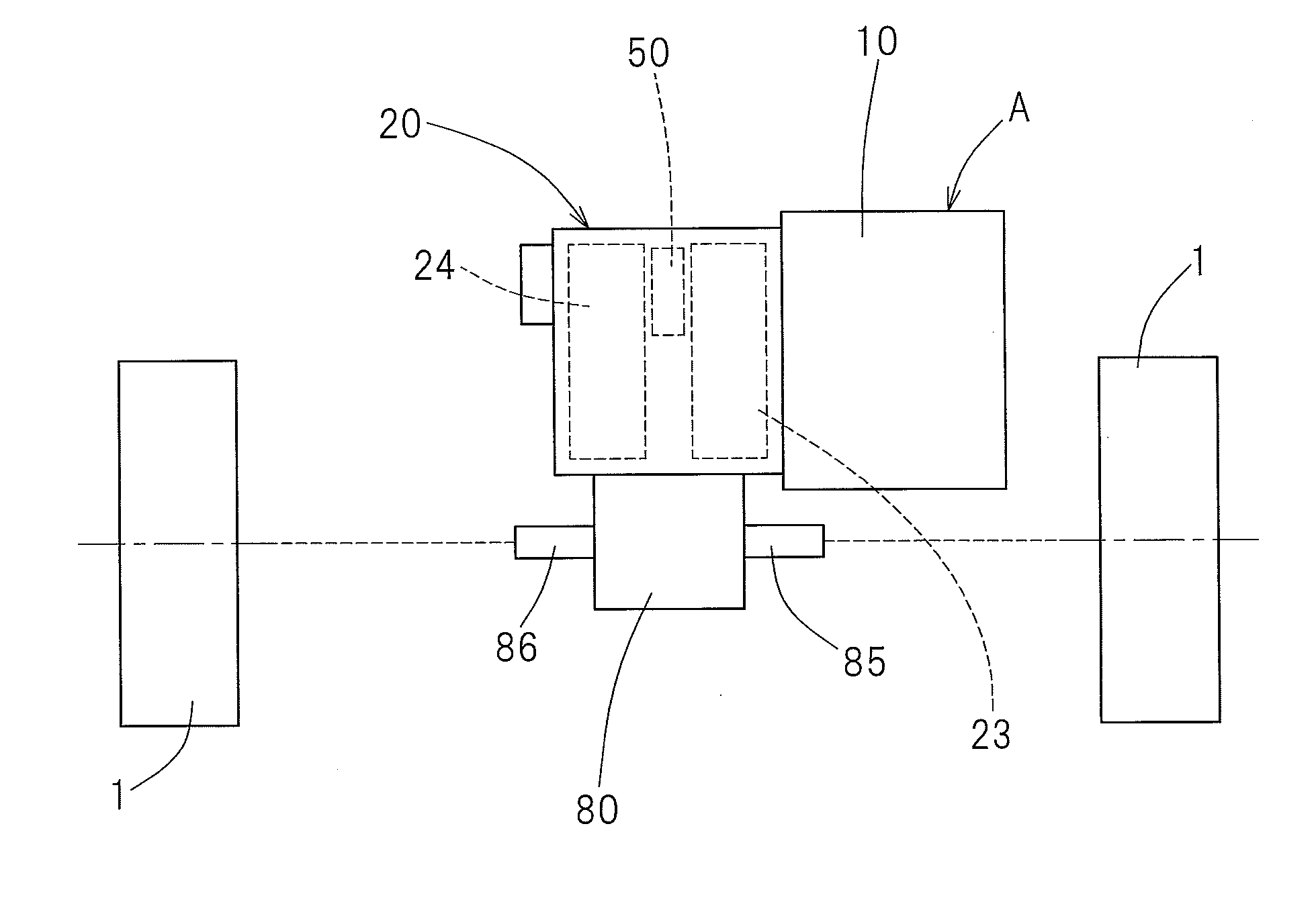
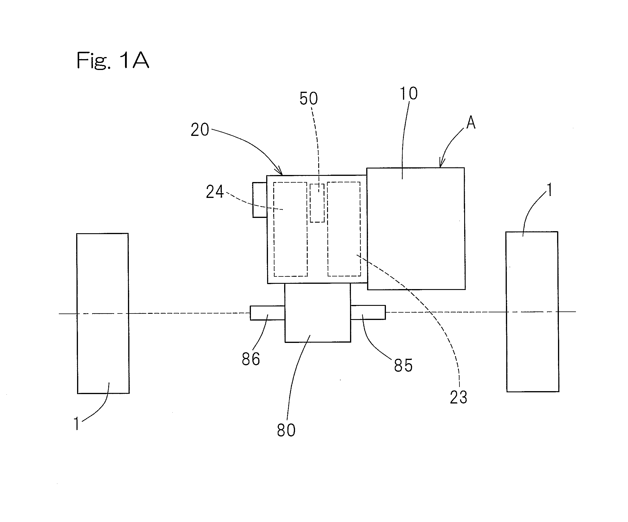
[0042]One embodiment of the present invention will now be described in detail with reference to the accompanying drawings. As shown in FIG. 1A, a vehicular motor drive device A includes an electric motor 10, and a speed reducer 20 interposed in a torque transmission system provided between the motor 10 and vehicle wheels 1 and 1. The speed reducer 20 in turn includes two gear trains 23 and 24 having smaller and larger speed reduction ratio, respectively, which are fixed speed reduction ratios, and a torque transmission path can be switched between those two gear trains 23 and 24 by means of a change gear ratio selector mechanism 50. The change gear ratio selector mechanism 50 referred to above is of a type capable of switching the changing ratio by coupling and decoupling a clutch as will be described later. An output of the speed reducer 20 is divided and transmitted to the left and right vehicle wheels 1 and 1 by a differential gear 80. The motor 10 is a synchronous motor such as,...


PUM


Abstract

A vehicular motor drive device is provided with an electric motor and a speed reducer having two gear trains capable of switching a fixed gear ratio. Driving force curves, which are determined depending on an output characteristic of the motor and represent a relationship between an output rotation speed in the respective gear train and an output torque, which is obtainable maximally at such output rotation speed, have a constant torque curve section, a gradually decreasing torque curve section and a constant speed curve section. The gear trains have respective speed reduction ratios such that the driving force curve of a gear train having a larger speed reduction ratio and the driving force curve of a gear train having a smaller speed reduction ratio continue to and partially overlap with each other in the gradually decreasing torque curve sections.

Description

CROSS REFERENCE TO THE RELATED APPLICATION[0001]This application is based on and claims Convention priority to Japanese patent application No. 2011-199008, filed Sep. 13, 2011, the entire disclosure of which is herein incorporated by reference as a part of this application.BACKGROUND OF THE INVENTION[0002]1. Field of the Invention[0003]The present invention relates to a vehicular motor drive device of a type, in which an electric motor is equipped as a drive source and is operable to transmit an output of the motor to a wheel after the speed thereof has been reduced, and also to an automobile having the vehicular motor drive device mounted thereon.[0004]2. Description of Related Art[0005]The electric motor has such a characteristic that the relationship between the rotation speed and the output torque attains a high efficiency within a certain range. For this reason, it is a common practice to transmit the rotation of such motor to a vehicle wheel through a speed reducer. The speed ...

Claims


Application Information

Patent Timeline
Patent Type & Authority Applications(United States)
IPC IPC(8): B60K6/20F16H3/00B60K1/00
CPCB60K6/20Y10S903/902F16H3/00B60K1/00B60L15/20B60L2240/421B60L2240/423B60L2260/28B60L50/16B60L50/61F16H3/10F16H2061/0216F16H2200/0021F16H2200/0034H02K7/116Y02T10/62Y02T10/64Y02T10/70B60K2001/001B60L2220/14Y02T10/72Y10T74/19219
Inventor ISOBE, FUMIHIROMAKINO, TOMOAKI
Owner NTN CORP
Why Eureka
Try Eureka