Dc-dc buck circuit

a buck circuit and buck circuit technology, applied in the direction of dc-dc conversion, power conversion systems, climate sustainability, etc., can solve the problems of inconvenient positioning of circuits and large volume of products, and achieve compact and effective circuit design, compact structure, and large output voltage

Inactive Publication Date: 2014-07-31
SIEMENS HEALTHCARE GMBH
View PDF4 Cites 8 Cited by
  • Summary
  • Abstract
  • Description
  • Claims
  • Application Information

AI Technical Summary

Benefits of technology

[0017]Unlike conventional DC-DC Buck circuits which are not compatible with DrMOS chips (FIG. 2), the DC-DC Buck circuit provided by the present invention is compatible with a DrMOS chip, thereby realizing a more compact and effective circuit design. The DC-DC Buck circuit provided by the present invention can supply a larger output voltage and satisfy the requirements of a wider range of applications than existing DC-DC Buck circuits which use DrMOS chips. Thus, the present invention uses an existing chip and makes only slight modifications to the circuit, so as to achieve the beneficial effects of a compact structure and a higher output voltage.

Problems solved by technology

Although this conventional synchronous DC-DC Buck circuit can produce a relatively high output voltage, the PWM control chip 10 in the circuit is only used for compatibility with the external discrete switch (e.g. MOSFET) circuits, i.e. the above-mentioned 5 external sub-circuits must be configured, with the result that the volume of the product is quite large, and positioning of circuits is inconvenient.

Method used


Image

  • Dc-dc buck circuit
  • Dc-dc buck circuit
  • Dc-dc buck circuit

Examples


Embodiment Construction

[0023]Particular embodiments of the present invention will now be explained with reference to the accompanying drawings, so that the technical features, object and effects of the present invention may be more clearly understood.

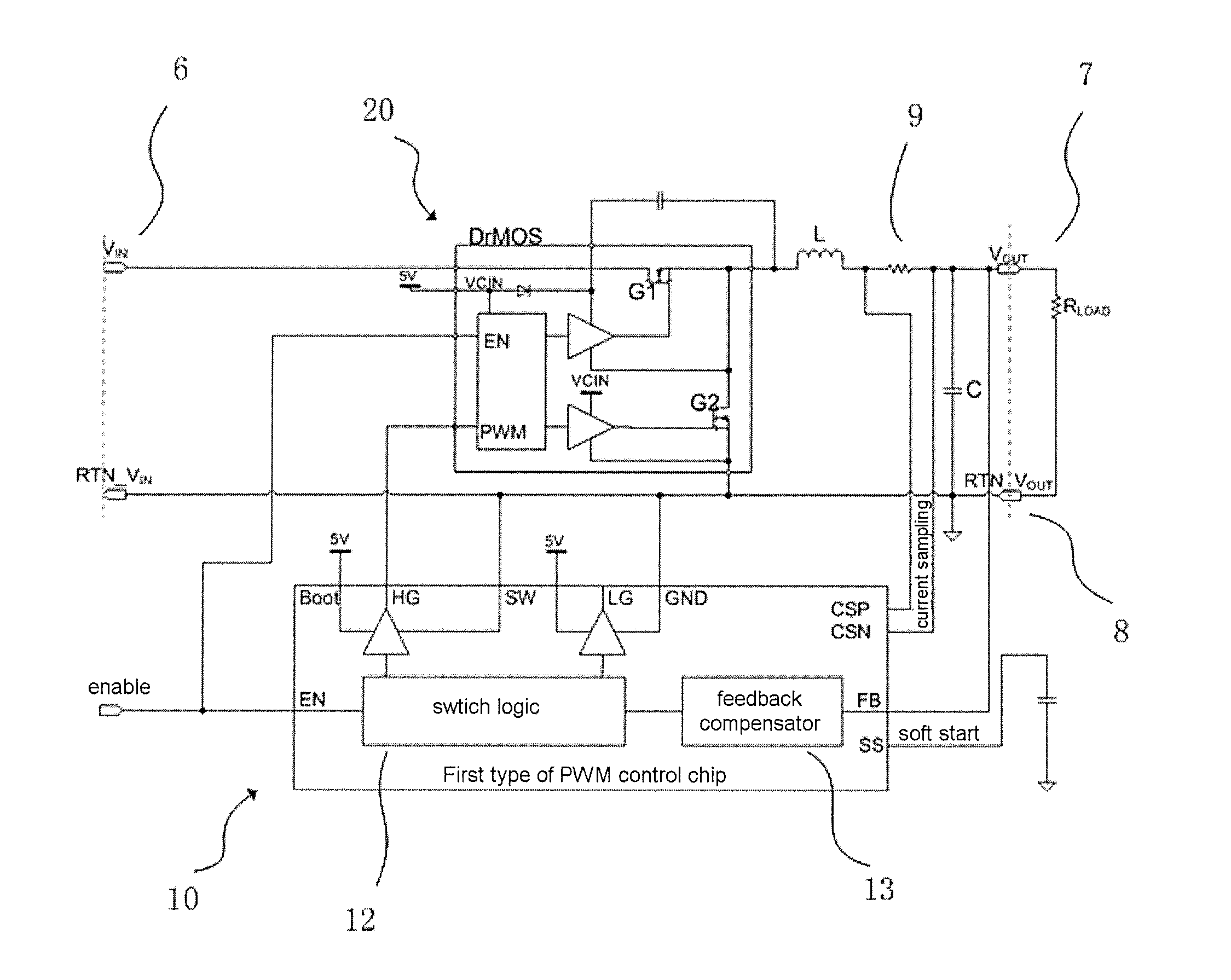
[0024]According to one embodiment of the present invention, a DC-DC Buck circuit is provided; FIG. 4 shows a circuit diagram of this DC-DC Buck circuit. The circuit comprises: a DC input terminal 6, a DC output terminal 7, a ground terminal 8, an inductor L, a capacitor C, a sampling resistor 9, an upper tube switch G1 and lower tube switch G2, a drive circuit and a PWM control circuit. The inductor L is located between the DC input terminal 6 and the DC output terminal 7; the capacitor C is located between the DC output terminal 7 and the ground terminal 8; the sampling resistor is located between the inductor L and the DC output terminal.

[0025]The upper tube switch G1, lower tube switch G2 and the drive circuit are formed as a DrMOS chip 20. The upper tube ...


PUM


Abstract

A DC-DC Buck circuit has a DC input terminal, a DC output terminal, a ground terminal, an inductor, a capacitor, a sampling resistor, a PWM control chip and a DrMOS chip. The output of the driver pin of the PWM control chip is unrelated to the voltage between the inductor and the sampling resistor. The DC-DC Buck circuit can produce a larger output voltage while also being compatible with a DrMOS chip.

Description

BACKGROUND OF THE INVENTION[0001]1. Field of the Invention[0002]The present invention relates overall to the technical field of direct current to direct current (DC-DC) power supplies, and more particularly to a DC-DC Buck circuit.[0003]2. Description of the Prior Art[0004]DC-DC conversion technology is currently widely used in fields such as household electrical appliances, digital products, and aeronautics and astronautics, with an ever increasing number of applications requiring the use of DC-DC power supply modules. A DC-DC Buck circuit is a circuit which makes the output voltage lower than the input voltage by switching or linear step-down, with both the input and the output being DC. There are two types of DC-DC Buck circuit, non-synchronous (asynchronous) and synchronous.[0005]FIG. 1 shows a diagram of a typical asynchronous DC-DC Buck circuit, which includes a switch S, inductor L, flyback diode VD, load Rload and capacitor C. When the switch S is conducting, the input volta...

Claims


Application Information

Patent Timeline
Patent Type & Authority Applications(United States)
IPC IPC(8): H02M3/156
CPCH02M3/1588Y02B70/10H02M3/158
Inventor LIU, YU YE
Owner SIEMENS HEALTHCARE GMBH
Why Eureka
Try Eureka