Multi-stage synchronous generator

a generator and multi-stage technology, applied in the direction of control systems, electric devices, generation protection through control, etc., can solve the problems of electrical components in the system making up the load, failures, and variations in the output voltage of the generator, so as to reduce the overall weight of the system and mitigate the consequences of a failure of the gcu elemen

Active Publication Date: 2020-08-20
LABINAL POWER SYST
View PDF33 Cites 2 Cited by
  • Summary
  • Abstract
  • Description
  • Claims
  • Application Information

AI Technical Summary

Benefits of technology

[0016]Embodiments of the present disclosure aim to improve upon systems for a multi-stage synchronous generator, in particular reducing the overall weight of the system while maintaining a system which operates within tightly controlled performance limits. This is particularly important in aircraft power generator syste...

Problems solved by technology

Although the electrical load driven by generators can be readily designed to cope with a range of input frequencies inherent to the variable output of a generator, one problem posed by such generators is that the output voltage of the generator can vary, depending particularly on rotational speed and the electrical load on the generator.
If the output voltage exceeds the operating limits of the electrical equipment, faults can arise.
If the generator's output voltage is too low, the electrical components in the system making up the load may not function correctly.
If the control element fails where the output voltage is too high, there is a potential for the ...

Method used


Image

  • Multi-stage synchronous generator
  • Multi-stage synchronous generator
  • Multi-stage synchronous generator

Examples


Embodiment Construction

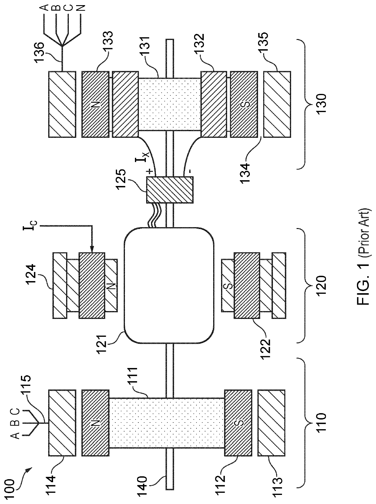
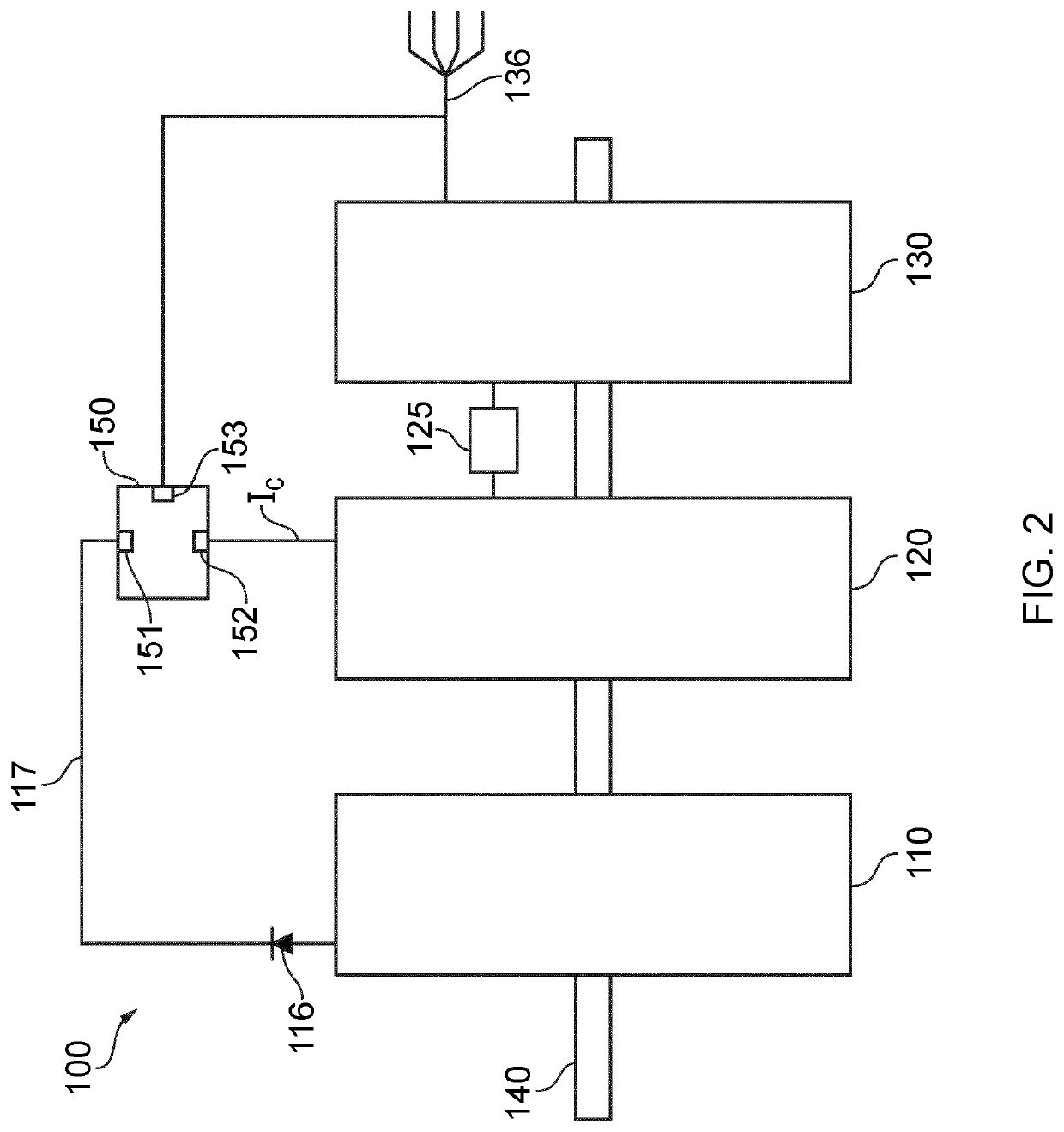
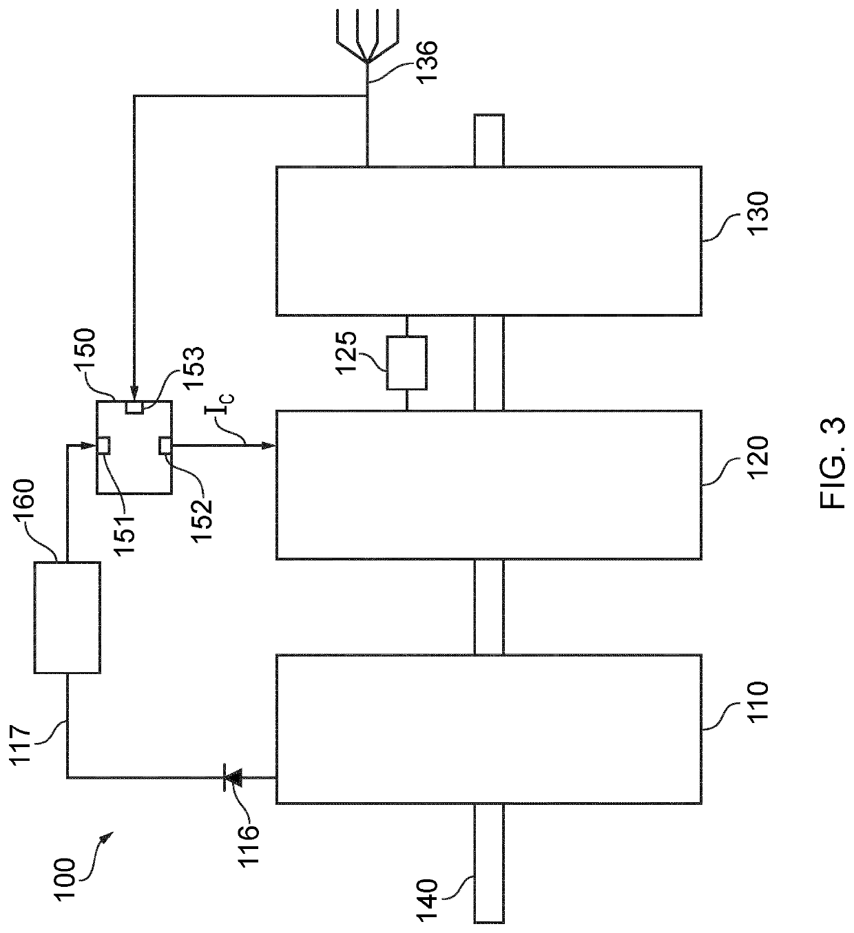
[0046]FIG. 3 shows an example of a multistage synchronous generator according to the present invention. It comprises a first stage 110, a second stage 120 and a third stage 130. In the embodiment shown in FIG. 3 the first stage 110, second stage 120 and third stage 130 are all mounted on input shaft 140, although examples of the invention can be implemented using any plurality of stages comprising a first stage, for providing an exciter current to a second stage of the plurality. A field current supply line 117 links an output of first stage 110 and the second stage 120. A rectifier 116 is preferably present in the field current supply line at the output of the first stage 110. Rectifier 116 is preferably a diode rectifier but can take the form of any component or system suitable for rectifying an alternating output of the first stage 110. If, for example, the first stage provides a direct current, then rectifier 116 may not be necessary. The field supply line also comprises a regul...


PUM


Abstract

The disclosed embodiments aim to improve upon existing multi stage generators for providing power to a load. In particular, embodiments of the invention include a regulator situated between the output of a pilot exciter and the main exciter of a multi stage generator system, the regulator arranged to limit the voltage available to a field current control element which sets the field current supplied to the main exciter.

Description

FIELD OF THE INVENTION[0001]The invention relates to a synchronous generator system, and in particular to variable speed generator systems used in aircraft.BACKGROUND OF THE INVENTION[0002]Typically, in gas turbine driven generators, rotational energy is provided to the generator rotors as a function of the speed of the turbine(s) driving the generator. In the context of an aircraft, for example, the rotational speed of the engine varies between ground idle (low speed), take off (high speed) and cruise (medium speed). This means that the generator operates over a range of input speeds. Many aircraft use constant frequency generators, with a speed changer interposed between the engine and generator, in order to provide the required electrical output within a range of acceptable frequencies, for the electrical equipment powered by the generator to function properly.[0003]It is beneficial in many applications, and particularly in aircraft, for generators to be as lightweight as possibl...

Claims


Application Information

Patent Timeline
IPC IPC(8): H02P9/48H02P9/00B64D41/00
CPCF01B23/10B64D41/00H02P2101/30H02P9/006H02P2101/25H02P9/48H02P9/10H02P9/302H02K19/36H02K19/38H02K21/02
Inventor DUDLEY, NEIL
Owner LABINAL POWER SYST
Why Eureka
Try Eureka