Magnetic bearing device and vacuum pump

a magnetic bearing and vacuum pump technology, applied in the direction of positive displacement liquid engines, piston pumps, liquid fuel engines, etc., can solve the problems of inability to influence the sampling effect of switching noise and attenuation of switching nois

Active Publication Date: 2014-07-31
SHIMADZU CORP
View PDF2 Cites 16 Cited by
  • Summary
  • Abstract
  • Description
  • Claims
  • Application Information

AI Technical Summary

Benefits of technology

[0007]A magnetic bearing device comprises: a pair of electromagnets provided for each of a plurality of control axes so as to face against a rotor shaft; a plurality of excitation amplifiers configured to perform PWM control to a voltage applied to each of the electromagnets, and supply an electromagnetic current on which a sensor carrier signal for detecting a change of a levitation position of the rotor shaft is overlapped to each of the electromagnets; a plurality of current sensors each configured to detect the electromagnetic current; and a controller configured to obtain magnetic levitation information of the rotor shaft by AD sampling of current detection signals from the plurality of current sensors and a sum signal obtained by adding the pair of current detection signals relating to the pair of electromagnets, and perform PWM control of the excitation amplifiers based on the magnetic levitation information. The controller performs PWM control so that a length of one of an on-duty period and an off-duty period of the PWM carrier signal is always longer than a predetermined time period based on an attenuation characteristic of a spike noise produced in the electromagnetic current, and performs the AD sampling after the predetermined time period passes from starting timing of one of the on-duty period and the off-duty period.

Problems solved by technology

However, when on-duty is around 0% or around 100% in PWM control, next switching timing comes before a switching noise attenuates sufficiently.
In such a case, even if the sampling is performed at a middle point in the voltage switching, an influence of a switching noise to the sampling is inevitable.

Method used


Image

  • Magnetic bearing device and vacuum pump
  • Magnetic bearing device and vacuum pump
  • Magnetic bearing device and vacuum pump

Examples


Embodiment Construction

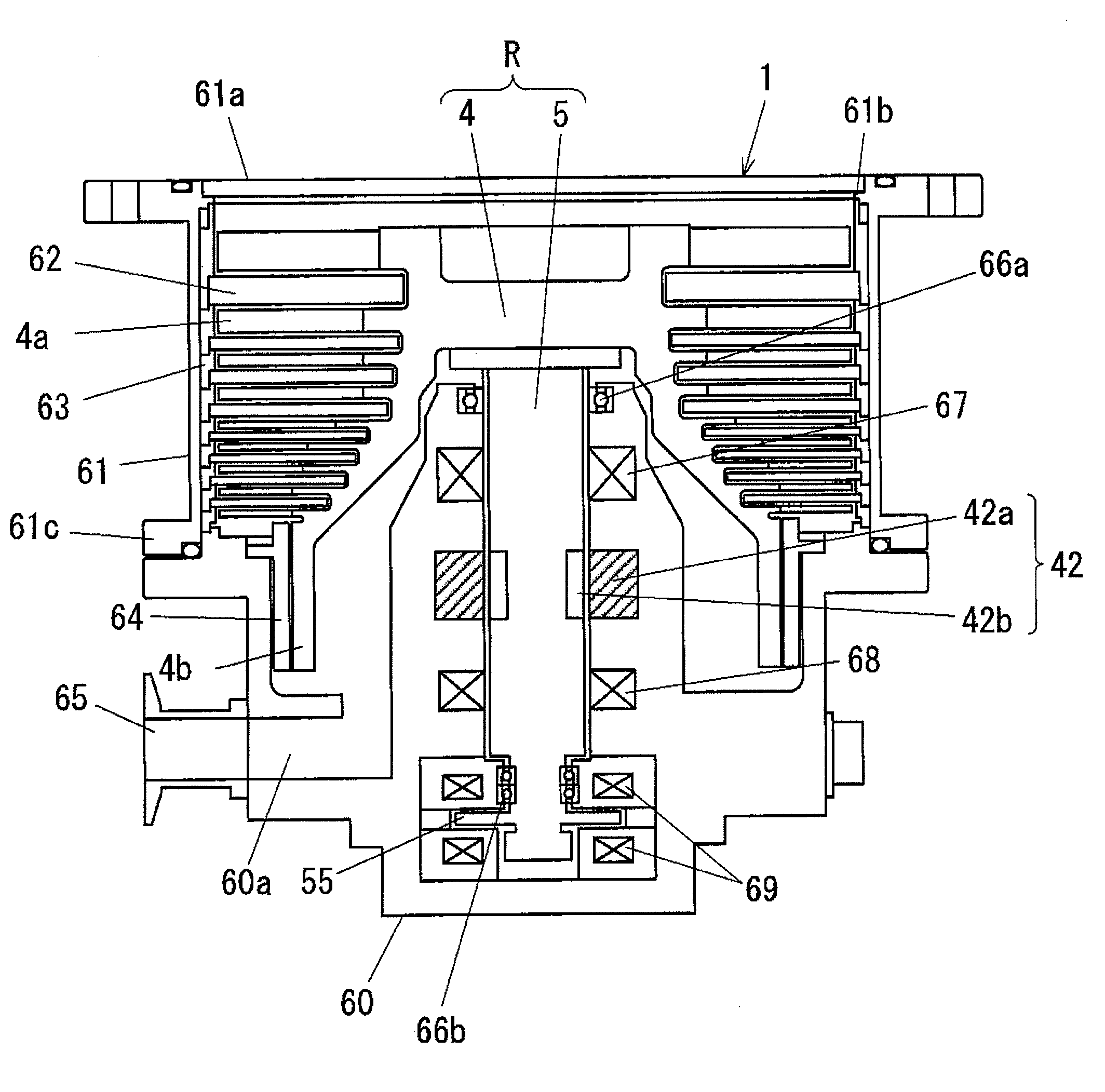
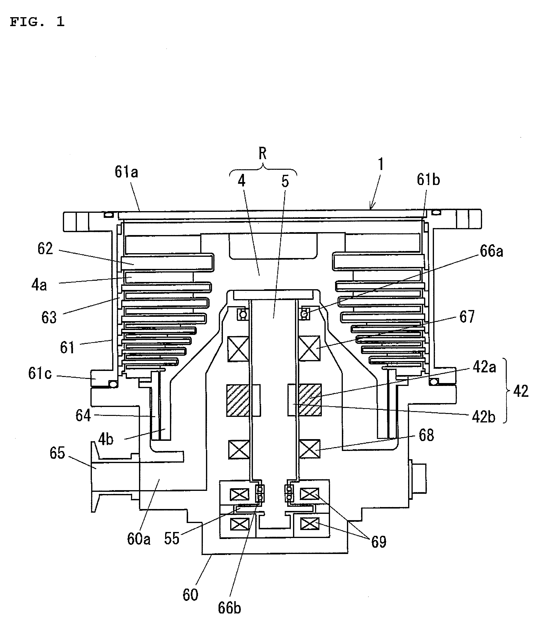
[0029]Hereinafter, embodiments for carrying out the present invention will be described with reference to the drawings. FIG. 1 is a diagram illustrating a schematic constitution of a vacuum pump of this embodiment, and shows a sectional constitution of a pump unit 1 of a magnetic levitation style turbo-molecular pump. The turbo-molecular pump is provided with the pump unit 1 illustrated in FIG. 1, and a control unit (not depicted) configured to drive the pump unit 1.

[0030]The pump unit 1 has a turbo pump stage composed of rotor blades 4a and fixed blades 62, and a drag pump stage (a thread groove pump) composed of a cylindrical section 4b and a screw stator 64. In this case, the thread groove is formed on the side of the screw stator 64, but the thread groove may be formed on the side of the cylindrical section 4b. The rotor blade 4a and the cylindrical section 4b as a rotation-side evacuating function section are formed on a pump rotor 4. The pump rotor 4 is fastened to a shaft 5. ...


PUM


Abstract

A magnetic bearing device comprises a controller configured to obtain magnetic levitation information of the rotor shaft by AD sampling of current detection signals from the plurality of current sensors and a sum signal obtained by adding the pair of current detection signals relating to the pair of electromagnets, and perform PWM control of the excitation amplifiers based on the magnetic levitation information. The controller performs PWM control so that a length of one of an on-duty period and an off-duty period of the PWM carrier signal is always longer than a predetermined time period based on an attenuation characteristic of a spike noise produced in the electromagnetic current, and performs the AD sampling after the predetermined time period passes from starting timing of one of the on-duty period and the off-duty period.

Description

BACKGROUND OF THE INVENTION[0001]1. Field of the Invention[0002]The present invention relates to a magnetic bearing device having an actuator function and a sensing function, and a vacuum pump having such a magnetic bearing device.[0003]2. Description of the Related Art[0004]In a known constitution for vacuum pumps provided with a magnetic bearing device, in order to realize downsizing, price reduction, and reliability improvement, a position sensor for detecting levitation displacement of a rotor is not provided, and an electromagnet for generating a levitation controlling force serves a sensing function in addition to a conventional actuator function (see JP 2009-275740 A, for example).[0005]In a conventional magnetic bearing device, an excitation current is supplied by applying a switching voltage from a PWM amplifier to an electromagnetic coil. In a magnetic bearing device having an actuator function and a sensing function, levitation position information of a rotor is obtained ...

Claims


Application Information

Patent Timeline
Patent Type & Authority Applications(United States)
IPC IPC(8): F16C32/04F04D29/058
CPCF04D29/058F16C32/0457F04D19/042F04D19/048F16C2360/45H02K7/09H02P6/182H02P21/24H02P21/36
Inventor KOZAKI, JUNICHIRONAGANO, YOSHIHIRO
Owner SHIMADZU CORP
Why Eureka
Try Eureka