Thermal Power Generation System and Method for Generating Thermal Electric Power

Active Publication Date: 2014-08-07
MITSUBISHI POWER LTD
View PDF7 Cites 23 Cited by
  • Summary
  • Abstract
  • Description
  • Claims
  • Application Information

AI Technical Summary

Benefits of technology

[0009]According to the embodiment of the present invention, the thermal power generation system can adjust the electric power supply required in the use of an unstable renewable energy source

Problems solved by technology

However, increasing the combustion temperature to a certain level or higher causes a reaction between nitrogen and oxygen in the air and thus produces nitride oxides (NOx), which requires various measures to be taken.
However, since the sunlight and wind pow

Method used


Image

  • Thermal Power Generation System and Method for Generating Thermal Electric Power
  • Thermal Power Generation System and Method for Generating Thermal Electric Power
  • Thermal Power Generation System and Method for Generating Thermal Electric Power

Examples


Example

First Embodiment

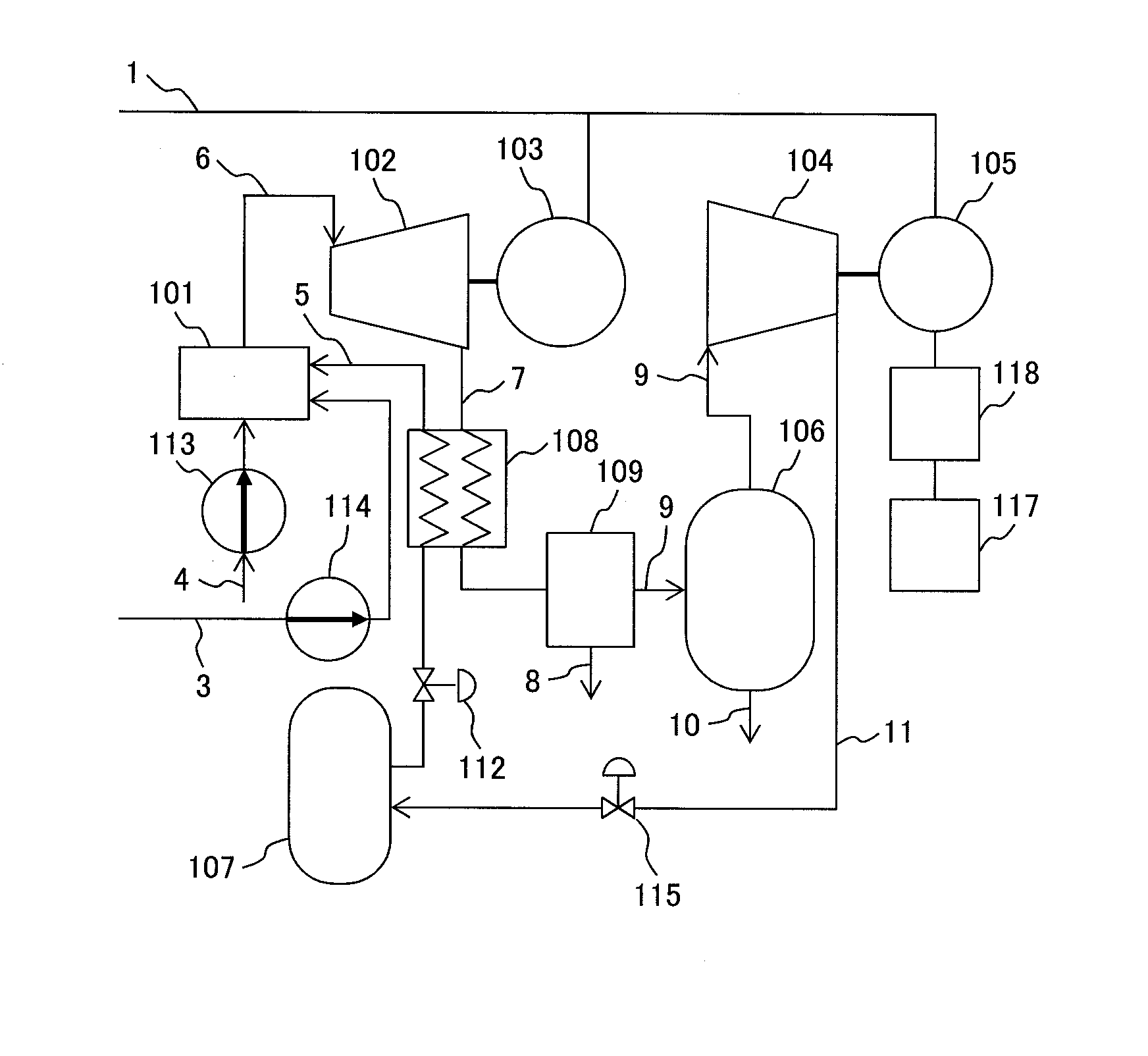
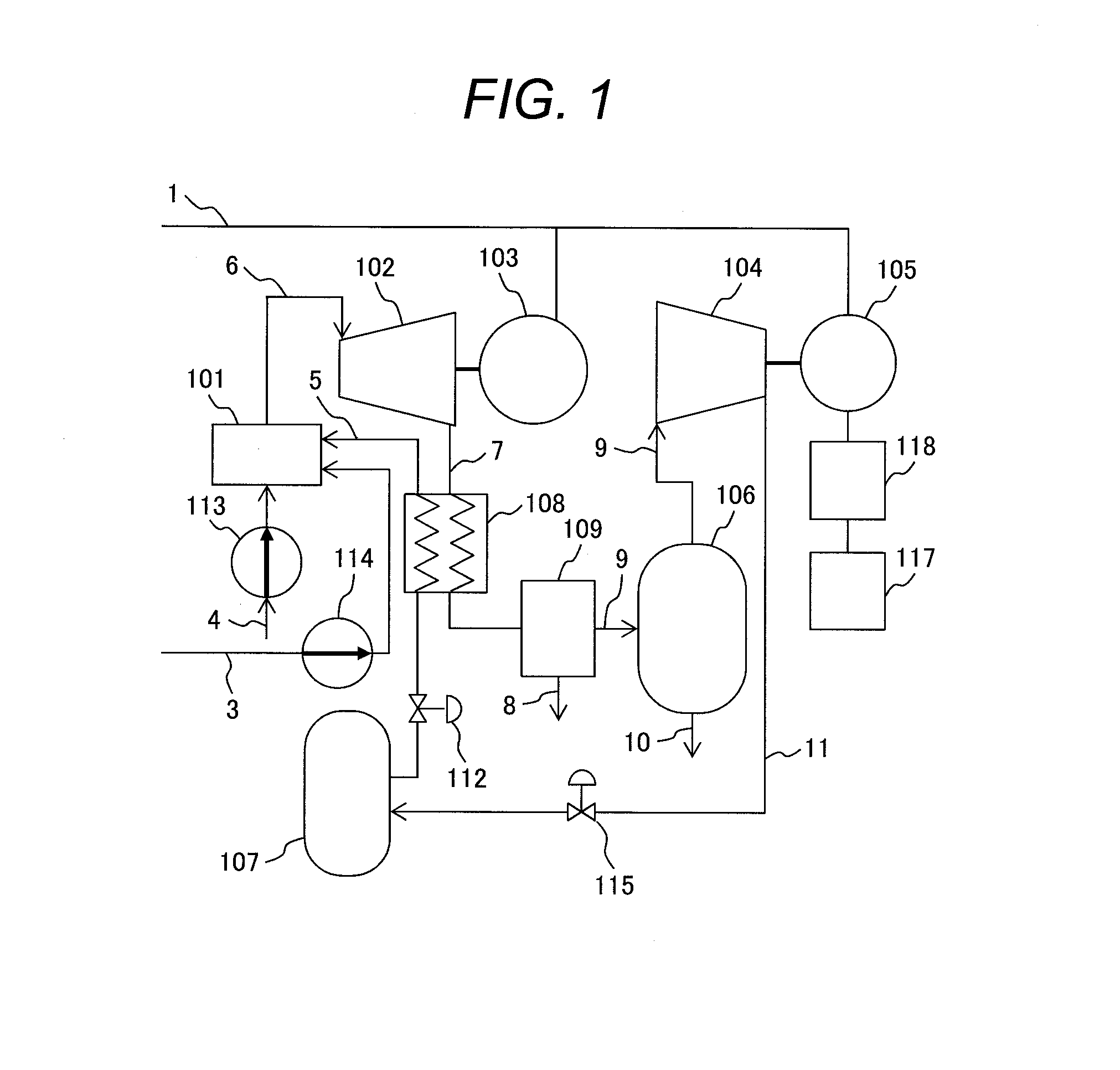
[0023]FIG. 1 is a system diagram of a thermal power generation system according to a first embodiment of the present invention. In FIG. 1, the thermal power generation system according to the first embodiment uses supercritical carbon dioxide 5 as a working fluid. The thermal power generation system includes a combustor 101 which burns oxygen 3 and fuel 4 with the supercritical carbon dioxide 5, a pump 114 used to supply the oxygen 3 to the combustor 101, a pump 113 used to supply the fuel 4 to the combustor 101, a supercritical CO2 turbine 102 which is driven by a mixed gas 6 of the supercritical carbon dioxide and water vapor supplied from the combustor 101, and a supercritical CO2 turbine generator 103 which is driven by the supercritical CO2 turbine 102.

[0024]In addition, the thermal power generation system of the first embodiment includes a regenerated heat exchanger 108 which heats the supercritical carbon dioxide 5 with turbine exhaust gas 7 emitted from the s...

Example

Second Embodiment

[0040]With reference to FIG. 4, the features of the second embodiment will be described. FIG. 4 is a system diagram of a thermal power generation system according to the second embodiment of the present invention. The description below does not provide explanations about the same components and configurations as those in the first embodiment, but focuses on different components and configurations.

[0041]In FIG. 4, the thermal power generation system according to the second embodiment includes a heat storage 120 which recovers and stores heat of high pressure supercritical carbon dioxide 11 obtained through compression by the supercritical CO2 compressor 104. With the heat storage 120, the heat generated during compression can be accumulated without going to waste and can be reused to heat the high pressure supercritical carbon dioxide 5 stored in the high pressure supercritical CO2 storage 107. Thus, the heat loss which occurs while the high pressure supercritical ca...

Example

Third Embodiment

[0044]FIG. 5 is a system diagram of a thermal power generation system according to the third embodiment of the present invention. The third embodiment possesses basic components common to the second embodiment. Therefore, descriptions of the common components to the second embodiment shown in FIG. 4 are omitted and the features of the third embodiment will be described by focusing on uncommon components with reference to FIG. 5.

[0045]In FIG. 5, the thermal power generation system according to the third embodiment includes a high pressure CO2 capturing unit 130 which captures high pressure supercritical carbon dioxide 30 from the high pressure supercritical CO2 storage 107 and sends it out, instead of capturing surplus carbon dioxide 10 from the low pressure CO2 storage 106. With the high pressure CO2 capturing unit 130, the CO2 emission into the air can be reduced and the CO2 captured is in a form available to EOR (Enhanced Oil Recovery) and other applications.


PUM


Abstract

A thermal power generation system includes a combustor burning oxygen and fuel with supercritical CO2, a turbine driven by the supercritical CO2 and water vapor fed from the combustor, a low-pressure supercritical CO2 storage storing low-pressure supercritical CO2 from the turbine, a compressor compressing the low-pressure supercritical CO2, a high-pressure supercritical CO2 storage storing high-pressure supercritical CO2 from the compressor, and a high-pressure supercritical CO2 feeder supplying between the high-pressure supercritical CO2 storage and the combustor, in which the high-pressure supercritical CO2 feeder supplies the high-pressure supercritical CO2 to the combustor at a constant pressure. Thus, the thermal power generation system can perform adjustment of an electric power supply required to use unstable renewable energy sources such as solar and wind power, can achieve high efficiency power generation with high temperature working fluid, and can reduce emissions of environmental load substances such as NOx and CO2.

Description

CLAIM OF PRIORITY[0001]The present application claims priority from Japanese Patent application serial No. 2013-018018, filed on Feb. 1, 2013, the content of which is hereby incorporated by reference into this application.BACKGROUND OF THE INVENTION[0002]1. Field of the Invention[0003]This invention relates to power generation systems, and more particularly to a thermal power generation system using a combustor and a gas turbine.[0004]2. Description of Related Art[0005]Technological development of thermal power generation systems equipped with a gas turbine which uses fossil fuel, such as natural gas, as a fuel has been encouraged in order to meet the demands to increase system efficiency and to cut NOx and CO2 emissions from the viewpoints of effective use of fossil fuels and the reduction of environmental loads. High system efficiency is achieved by increasing the pressure ratio and combustion temperature. However, increasing the combustion temperature to a certain level or higher...

Claims


Application Information

Patent Timeline
IPC IPC(8): F01K13/00
CPCF01K13/00F02C3/34F02C3/30F02C6/18F05D2210/12F05D2210/14Y02E20/16F01K25/103Y02E20/34Y02E50/10Y02E60/16
Inventor NUMATA, SHOHEINAKANO, SUSUMUSHIBATA, TAKANORIARAKI, HIDEFUMI
Owner MITSUBISHI POWER LTD
Why Eureka
Try Eureka