Laminate Compaction Using Magnetic Force

a magnetic force and compaction technology, applied in the field of composite parts fabrication, can solve the problems of reducing the compaction pressure applied to the fiber pre-form, unable to fully form a multi-ply charge into these corners, and unable to achieve adequate compaction of the formed composite charge, etc., to achieve the effect of reducing bridging, reducing bridging, and being easy to install

Active Publication Date: 2014-08-07
THE BOEING CO
View PDF4 Cites 6 Cited by
  • Summary
  • Abstract
  • Description
  • Claims
  • Application Information

AI Technical Summary

Benefits of technology

[0008]The disclosed embodiments provide magnetic pressure intensifier device which may be used to locally intensify compaction pressure applied to a formed, composite laminate charge using the magnetic force supplied by one or more magnets. The amount of magnetic force, and thus the level of compaction pressure, may be adjusted by changing the position of the magnet on the device. The device applies constant compaction pressure throughout de-bulking, compaction or curing, and moves in any of three dimensions along with the charge as it is being compacted. The device is simple in construction, easily installed and is compatible with existing composite laminate fabrication processes. The device is effective in reducing bridging and increasing fiber fraction in areas of the part having a tight radius. The device may also be used to hold parts in a fixture during assembly.

Problems solved by technology

Depending on the fabrication technique used and the geometry of the part, achieving adequate compaction of the formed composite charge may present challenges.
Similarly, where the forming tool has features, such as relatively sharp inside corners, it may be difficult to fully form a multi-ply charge into these the corners.
When the resin infusion technique is used, compaction pressure applied to the fiber pre-form may be lost as the resin is being introduced.
Regardless of the fabrication technique, the application of inadequate compaction pressure may result in the finished part exhibiting resin rich zones that have less than a desired fiber fraction, potentially affecting part performance.
Pressure intensifiers had been developed to intensify the amount of compaction pressure that is applied to local areas of a composite charge, but each has limitations.
In some applications, tool or part geometries may prohibit the use of known pressure intensifiers.

Method used


Image

  • Laminate Compaction Using Magnetic Force
  • Laminate Compaction Using Magnetic Force
  • Laminate Compaction Using Magnetic Force

Examples


Embodiment Construction

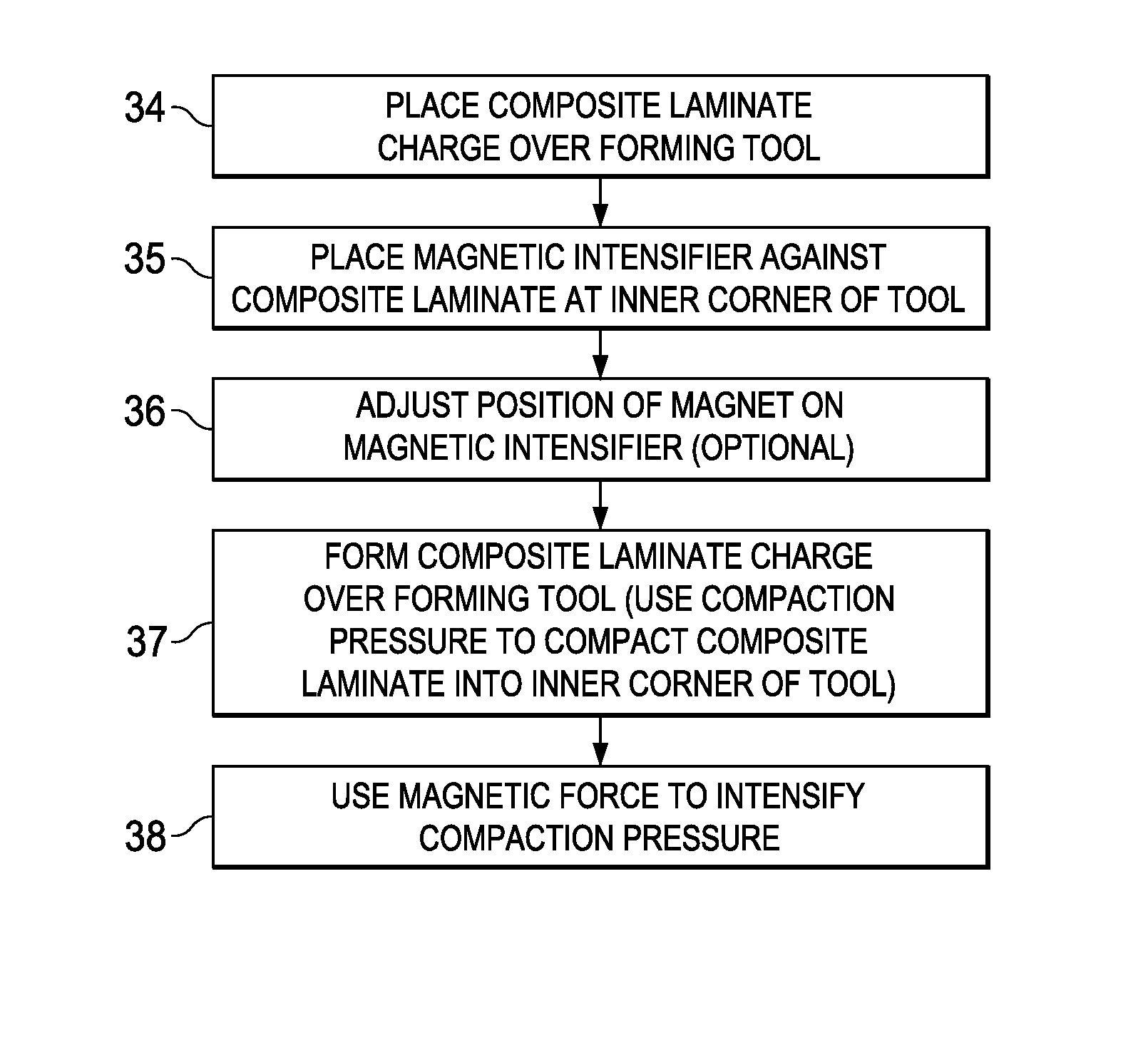
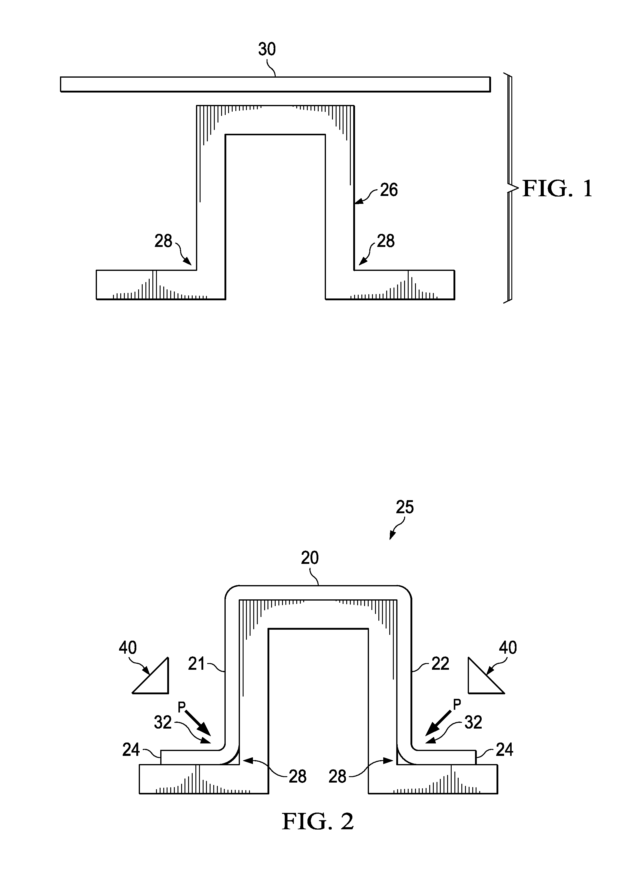
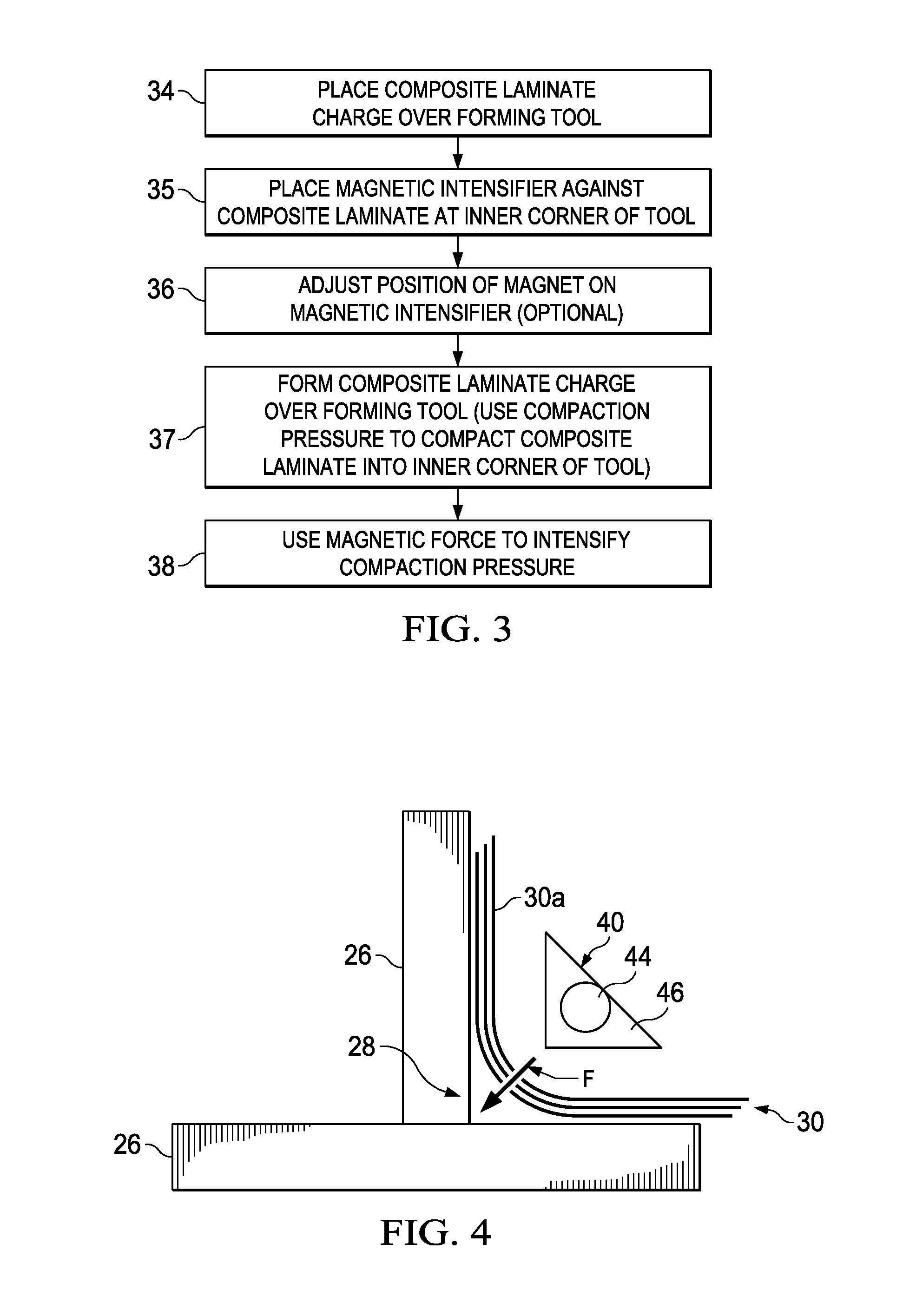
[0030]Referring first to FIGS. 1, 2 and 3, a multi-ply uncured composite laminate charge 30 may be formed over a male tool 26. The charge 30 may comprise a layup of pre-preg, however as will be discussed later the charge 30 may comprise a dry fiber preform that is subsequently infused with resin within a mold (not shown). In the example shown in FIGS. 1 and 2, the formed part is a hat-shaped stringer 25 (FIG. 2), comprising three legs 20, 21, 22 and a pair of outwardly turned flanges 24. Each of the flanges 24 transitions to one of the legs 21, 22 through an inner radius 32 which is formed within a 90° inside corner 28 of the tool 26. In order to form each inner radius 32 into an inside corner 28, a compaction pressure P is applied to the laminate charge 30 at the inside corners 28. As will be described in more detail below, in accordance with the disclosed embodiments, the necessary compaction pressure P is applied using a magnetic force generated by a magnetic pressure intensifier...


PUM

PropertyMeasurementUnit
temperaturesaaaaaaaaaa
magnetic forceaaaaaaaaaa

Abstract

A device uses magnetic force generated by a magnet to intensify compaction pressure applied to a composite laminate.

Description

BACKGROUND INFORMATION[0001]1. Field[0002]The present disclosure generally relates to the fabrication of composite parts, and deals more particularly with a method and device for compacting composite plies against a tool.[0003]2. Background[0004]Composite parts comprising fiber reinforced polymer resins may be fabricated using any of several techniques. In one technique, a multi-ply, fiber pre-preg charge is laid up and drape formed over a tool, following which the formed charge is compacted and cured. In another technique, a dry fiber pre-form is placed in a mold, vacuum bagged and then infused with resin to produce the desired part shape. The resin infused pre-form is then cured using autoclave or out-of-autoclave processes.[0005]Depending on the fabrication technique used and the geometry of the part, achieving adequate compaction of the formed composite charge may present challenges. For example, bridging of the vacuum bag over some areas of the charge may prevent full compactio...

Claims


Application Information

Patent Timeline
Patent Type & Authority Applications(United States)
IPC IPC(8): B32B37/10
CPCB32B37/10B29C43/203B29C43/36B29C70/42B29C2043/3613B29C2043/3211B29L2031/003B29C70/549
Inventor CHILDRESS, JAMES J.BAKER, ALAN W.KLEWIADA, MARK
Owner THE BOEING CO
Why Eureka
Try Eureka