Hybrid bootstrap capacitor refresh technique for charger/converter

a capacitor refresh and hybrid technology, applied in pulse technique, process and machine control, instruments, etc., can solve the problems of not being able to charge up c/sub>boot /sub>to a sufficiently high voltage, short turn-on time, and negative current not desirable for dcm operation

Active Publication Date: 2014-08-07
APPLE INC
View PDF18 Cites 55 Cited by
  • Summary
  • Abstract
  • Description
  • Claims
  • Application Information

AI Technical Summary

Benefits of technology

[0026]In some embodiments, both the high-side switching MOSFET and the low-side switching MOSFET are N-type MOSFETs.
[0027]The disclosed embodiments also provide a charging circuit. This charging circuit includes a DC power connector. The charging circuit also includes a synchronous switching converter coupled to the DC power connector and configured to convert a DC input voltage to a DC output voltage. This synchronous switching converter further includes a high-side switching MOSFET coupled between an input node and a first node. The synchronous switching converter also includes a low-side switching MOSFET coupled between the first node and a ground node and in series with the high-side switching MOSFET. The synchronous switching converter also includes an inductor coupled to the first node. This converter additionally includes a bootstrap capacitor coupled to the high-side switching MOSFET to provide turn-on voltage for the high-side switching MOSFET. Furthermore, the converter includes a main refresh circuit coupled to the bootstrap capacitor and configured to refresh the bootstrap capacitor during a first operating mode of the synchronous switching converter. Moreover, the converter includes an auxiliary refresh circuit coupled to the main refresh circuit and the bootstrap capacitor and configured to refresh the bootstrap capacitor during a second operating mode of the synchronous switching converter.

Problems solved by technology

Limited by total impedance of the refresh loop, this refresh operation demands enough turn-on time of the low-side MOSFET.
However, these conventional refresh techniques for CBOOT refresh have a number of drawbacks.
However, when the load is light, inductor current IL drops to near zero, thus the turn-on time is very short, and even zero (some inductor current detection techniques turn off the low-side MOSFET when IL is near zero).
Consequently, there is not enough time to charge up CBOOT to a sufficiently high voltage in light load conditions using the conventional refresh techniques.
However, such a negative current is not desirable for the DCM operation.
This undesired input voltage increase can lead to over-voltage stress.
Additionally, when the converter output has an energy-storage component such as a battery, the boost-back condition can also cause unwanted battery discharges current.
Similar problem happens when the converter is transitioned into performing pulse-frequency modulation (PFM) switching at a light load condition, wherein the switching frequency is significantly reduced (e.g., down from a few hundred kHz to a few kHz), and the refresh pulse, as well as the negative induct current can happens in the time interval between two PFM pulses.
Another drawback of the conventional refresh techniques is associated with a 4-switch buck-boost converter.
Unfortunately, in the case of a 4-switch buck-boost converter, allowing such a refresh operation to occur means that normal operation has to be interrupted.
Note that the same problem also occurs when the buck-boost converter is under buck-mode operation.

Method used


Image

  • Hybrid bootstrap capacitor refresh technique for charger/converter
  • Hybrid bootstrap capacitor refresh technique for charger/converter
  • Hybrid bootstrap capacitor refresh technique for charger/converter

Examples


Embodiment Construction

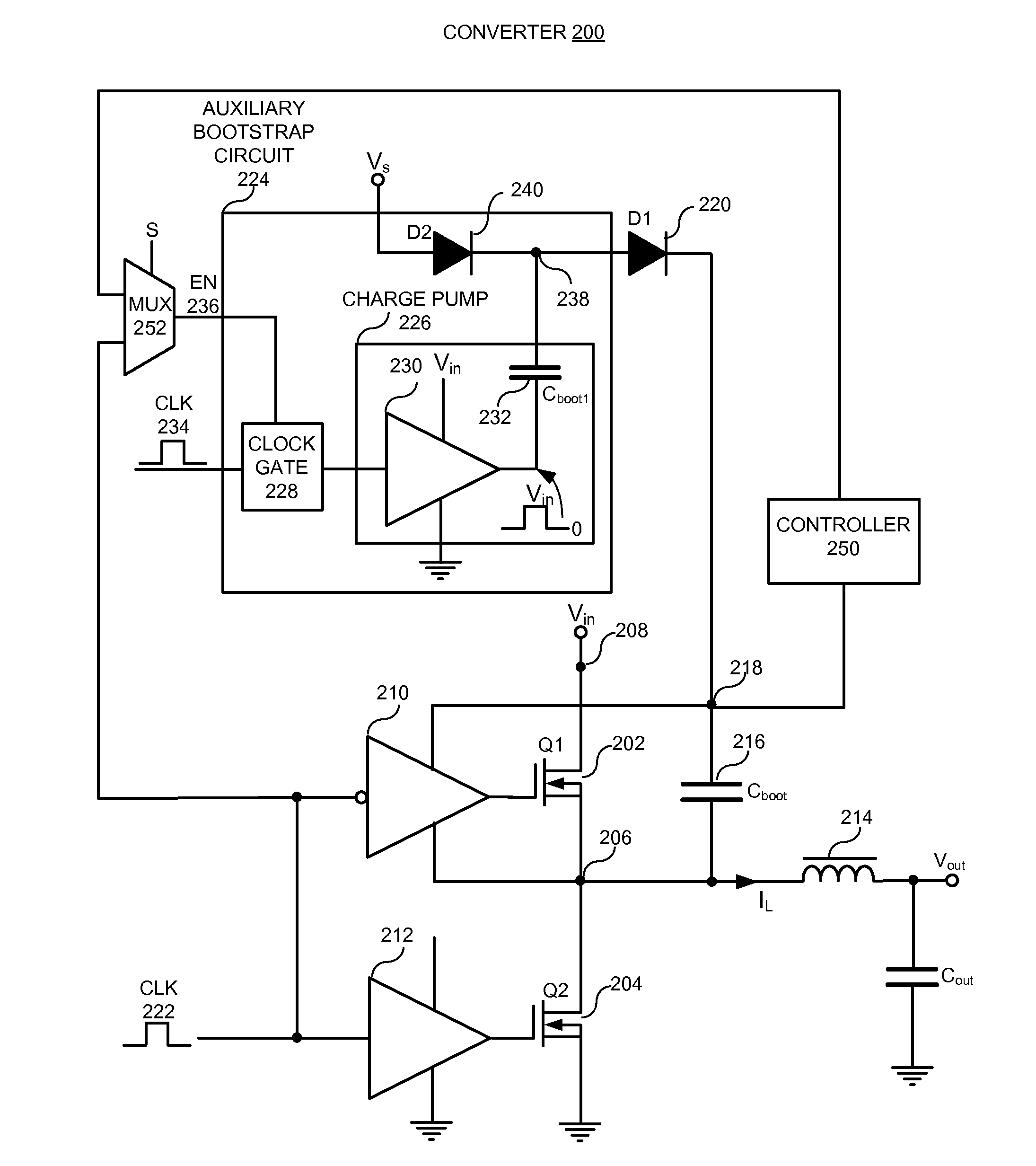
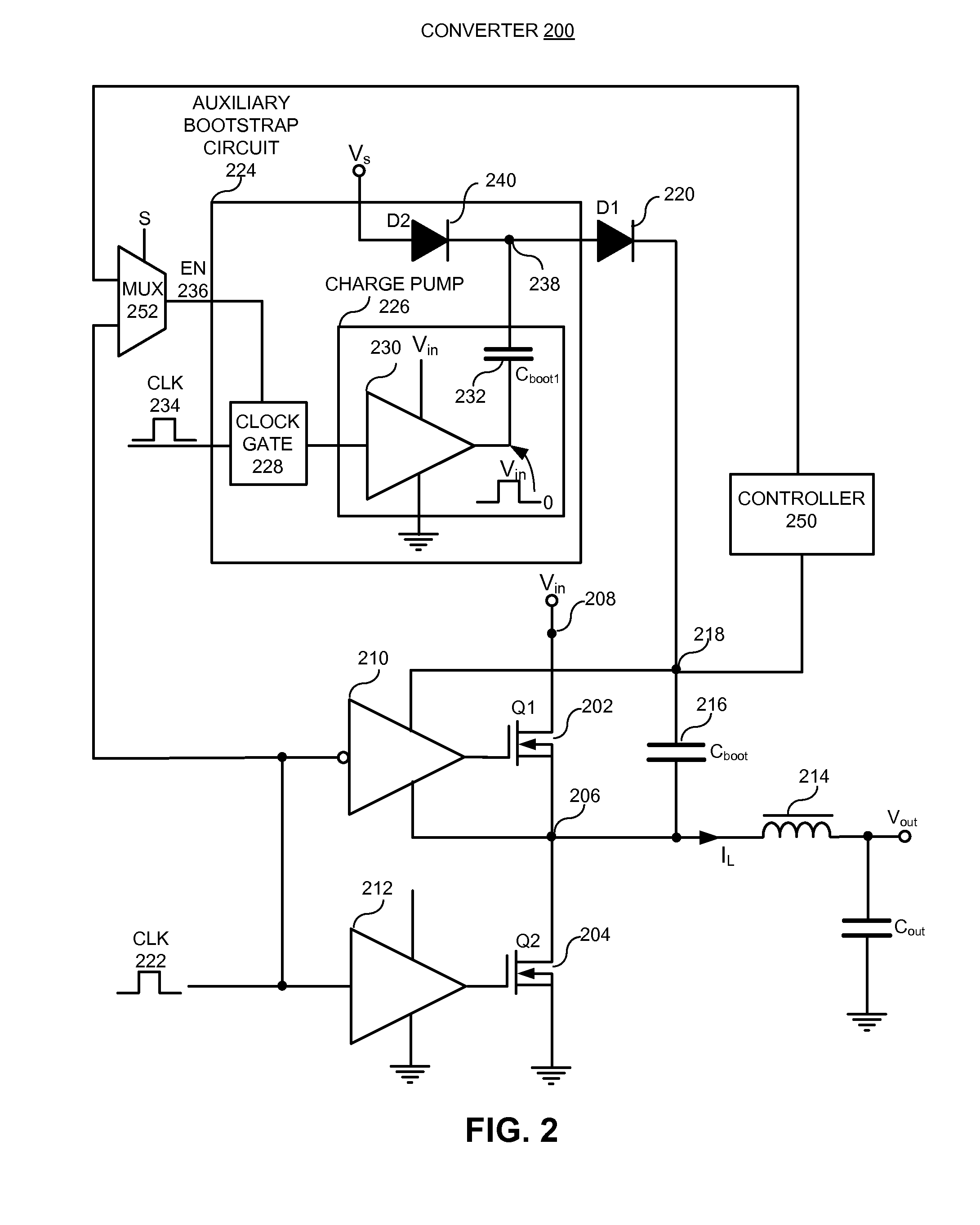
[0035]The disclosed embodiments provide synchronous switching DC / DC converter designs which can be used to supply DC power to computing devices (e.g., desktop computers, laptop computers, tablet computers, portable media players, smartphones, and / or other modern computing devices), battery chargers, and electrical vehicles, among other applications.

[0036]In particular embodiments, this DC / DC converter includes a high-side switching MOSFET coupled between an input node and a first node. The DC / DC converter also includes a low-side switching MOSFET coupled between the first node and a ground node and in series with the high-side switching MOSFET. This DC / DC converter additionally includes a bootstrap capacitor coupled to the high-side switching MOSFET to provide turn-on voltage for the high-side switching MOSFET. Furthermore, the DC / DC converter includes a main refresh circuit coupled to the bootstrap capacitor and is configured to refresh the bootstrap capacitor during a first operat...


PUM


Abstract

The disclosed embodiments provide a synchronous switching converter that converts a DC input voltage into a DC output voltage. This synchronous switching converter includes a high-side switching MOSFET coupled between an input node and a first node. The converter also includes a low-side switching MOSFET coupled between the first node and a ground node and is in series with the high-side switching MOSFET. This converter additionally includes a bootstrap capacitor coupled to the high-side switching MOSFET to provide turn-on voltage for the high-side switching MOSFET. Furthermore, the converter includes a main refresh circuit coupled to the bootstrap capacitor and is configured to refresh the bootstrap capacitor during a first operating mode of the synchronous switching converter. Moreover, the converter includes an auxiliary refresh circuit coupled to the main refresh circuit and the bootstrap capacitor and is configured to refresh the bootstrap capacitor during a second operating mode of the converter.

Description

RELATED APPLICATION[0001]This application hereby claims priority under 35 U.S.C. §119 to U.S. Provisional Application No. 61 / 761,156, entitled “HYBRID BOOT-CAP REFRESH TECHNIQUE FOR CHARGING / CONVERTER,” by inventors Bin Chen et al. filed on 5 Feb. 2013 (Atty. Docket No.: APL-P18318USP1).BACKGROUND[0002]1. Field[0003]The disclosed embodiments relate to the design of DC / DC converters. More specifically, the disclosed embodiments relate to designing bootstrap capacitor refresh circuits for synchronous switching DC / DC converters.[0004]2. Related Art[0005]Switched-mode power converters (or “switching converters”) are a type of DC / DC power converter which incorporates a switching regulator to convert electrical power from one DC voltage to another DC voltage more efficiently. Switching converters are commonly used in modern computing devices (e.g., both desktop and laptop computers, tablet computers, portable media players, smartphones, and / or other modern computing devices), battery char...

Claims


Application Information

Patent Timeline
Patent Type & Authority Applications(United States)
IPC IPC(8): G05F3/08H02J7/00H02M1/00
CPCH02J7/0052G05F3/08H02J7/00H02M3/1582H02M3/1588H03K2217/0063H03K2217/0081H02M1/0006H02M1/0032Y02B70/10H02M3/285H02J2207/20Y02B40/00Y02T90/12
Inventor CHEN, BINYE, MAOHU, YONGXUAN
Owner APPLE INC
Why Eureka
Try Eureka