Method of forming a bonded assembly

a technology of bonded assemblies and bonded parts, which is applied in the direction of manufacturing tools, transportation and packaging, non-electric welding apparatus, etc., can solve the problems of low penetration weld and high strength weld, and achieve the effect of small tab and little machining tim

Active Publication Date: 2014-08-07
ROLLS ROYCE PLC
View PDF2 Cites 4 Cited by
  • Summary
  • Abstract
  • Description
  • Claims
  • Application Information

AI Technical Summary

Benefits of technology

[0019]Advantageously, the tab positions the electron beam weld away from a final geometry of the bonded assembly, thereby ensuring the final geometry of the bonded assembly does not contain any heat affected zones produced by the electron beam welding process. Since the electron beam welding is only used to seal part of the edge of the bond interface region, a relatively small tab can be provided, and hence only a relatively small

Problems solved by technology

Furthermore, the use of laser welding for at least some of the bond interface region results in a

Method used


Image

  • Method of forming a bonded assembly
  • Method of forming a bonded assembly
  • Method of forming a bonded assembly

Examples


Embodiment Construction

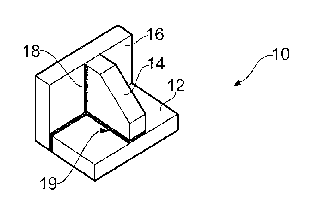
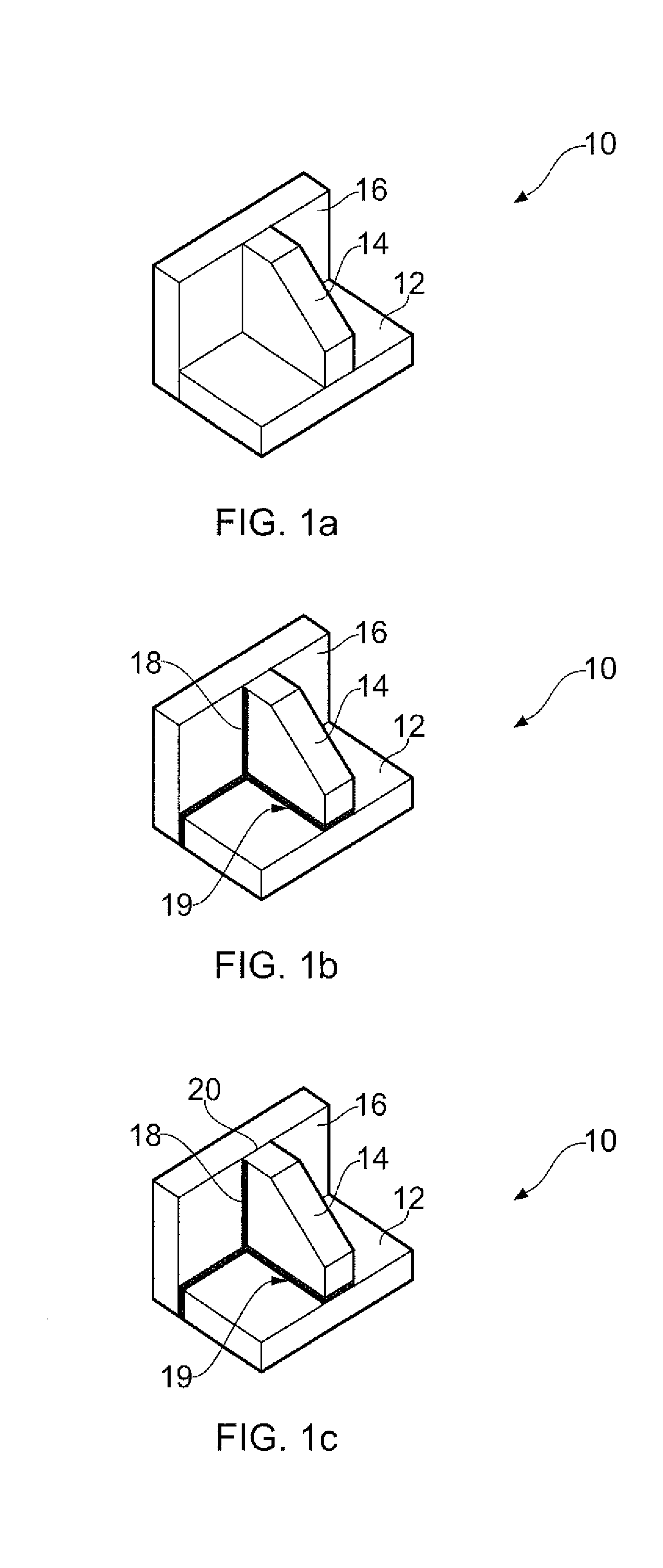
[0027]FIG. 1 shows an assembly 10 comprising first 12, second 14 and third 16 parts. The invention could also be used to bond assemblies comprising fewer or greater numbers of parts. The parts 12, 14, 16 could comprise any suitable metal that can be welded, provided the material is substantially non-porous, or has at least a non-porous outer surface, such that gases cannot penetrate the surface of the parts 12, 14, 16 during a HIP process. In the described embodiments, the parts 12, 14, 16 comprise titanium alloy.

[0028]In a first step, shown in FIG. 1a, the first, second and third parts 12, 14, 16 are abutted together in a required relative position. The parts 12, 14, 16 may be clamped together suing any suitable means such as a jig or fixture. Once abutted together, the parts 12, 14, 16 define a bond interface region therebetween at the surface of the parts 12, 14, 16 where the parts abut. Once the assembly is bonded, the bond interface region forms a diffusion bond between the par...


PUM

PropertyMeasurementUnit
Pressureaaaaaaaaaa
Vacuumaaaaaaaaaa

Abstract

A method of forming a bonded assembly (10). The method comprises: providing at least first and second parts (12, 14) of an assembly (10) to be bonded; assembling the first and second parts (12, 14) in a required relative position to define a bond interface region therebetween; sealing part way along an edge (18) of the bond interface region using laser beam welding to define a cavity between the first and second parts (12, 14); in a vacuum environment, sealing the remainder of the edge (20) of the bond interface region using electron beam welding to form a fluid tight seal around the cavity; and applying heat and pressure to an external surface of the cavity to diffusion bond the first and second parts (12, 14) together.

Description

FIELD OF THE INVENTION[0001]The present invention relates to a method of forming a bonded assembly, and a bonded assembly formed by the method.BACKGROUND TO THE INVENTION[0002]Conventional methods of manufacture for bonded assemblies such as support structures, casings, discs and drums for gas turbine engines often result in low “fly to buy” ratios (i.e. result in large amounts of wasted material) and require significant amounts of machining to achieve the finished component. Consequently, such conventional methods are expensive both in terms of raw materials and labour. Near net shape manufacture can offer greatly improved fly to buy ratios and large component cost reductions from greatly improved material utilisation rates and reductions in finishing operations such as machining, which may improve factory capacity and throughput.[0003]Hot Isostatic Pressing (HIP) diffusion bonding is one manufacturing method which is suitable for producing high integrity and low cost near net shap...

Claims


Application Information

Patent Timeline
IPC IPC(8): B23K15/00B23K15/06B32B15/01B23K26/20
CPCB23K15/0006B32B15/01B23K26/203B23K15/06B23K15/0046B23K20/021B23K26/21B23K26/211B23K26/346B23K28/02Y10T428/12493
Inventor BOSWELL, JOHN HAROLDCLARK, DANIELCARPENTER, CHARLES RICHARDKENNEDY, ANDREW RICHARD
Owner ROLLS ROYCE PLC
Why Eureka
Try Eureka