
Tissue sealing method

a tissue sealing and tissue technology, applied in the field of electrosurgical medical devices, can solve the problems of unintended tissue damage, unintended tissue damage, and failure to seal, and achieve the effects of improving coagulation and sealing of rf tissue, efficient use of target region, and better control of target tissue area

Inactive Publication Date: 2014-08-07
SPINNAKER MEDICAL
View PDF2 Cites 12 Cited by
  • Summary
  • Abstract
  • Description
  • Claims
  • Application Information

AI Technical Summary

Benefits of technology

This solution improves seal consistency, reduces tissue damage, and enhances surgical precision by efficiently using heat within the target area, minimizing energy requirements and improving visibility during laparoscopic procedures.

Problems solved by technology

However, consistent performance is a common issue with these types of devices, resulting in failed seals, blood loss and safety concerns.
In addition, many instances of excessive energy delivery at the seal site results in over desiccated, charred tissue, sticking and unintended thermal damage to surrounding tissue structures.
A major cause of unintended tissue damage is the generation of boiling fluid and steam during the sealing process.
This hot vapor and fluid is released under pressure along the outer periphery of the jaws and can damage tissue more than 10 mm away from the target site.

Method used


Image

  • Tissue sealing method
  • Tissue sealing method
  • Tissue sealing method

Examples


Embodiment Construction

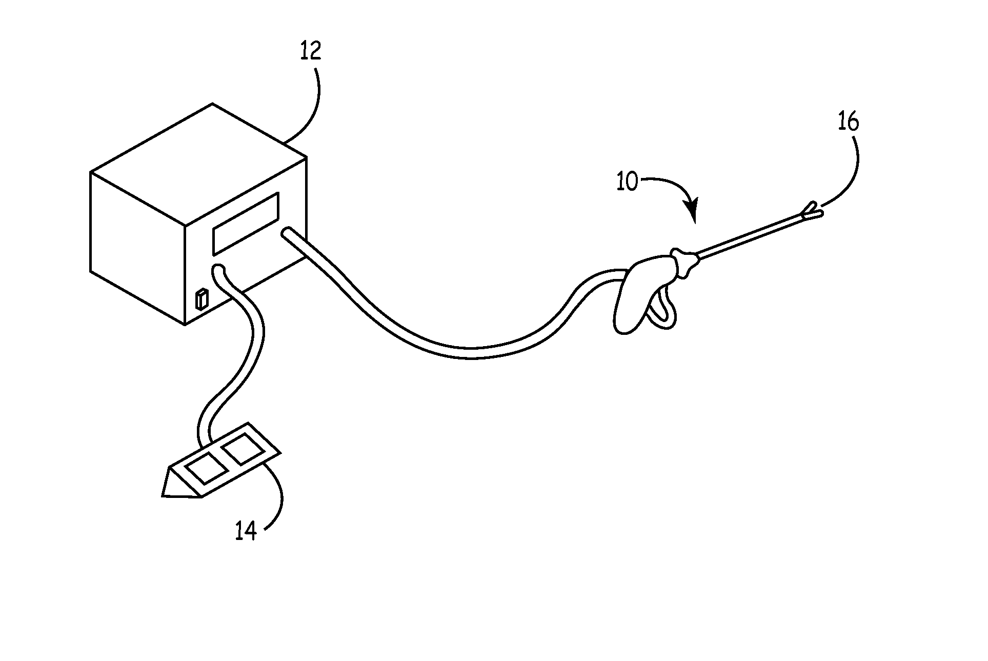
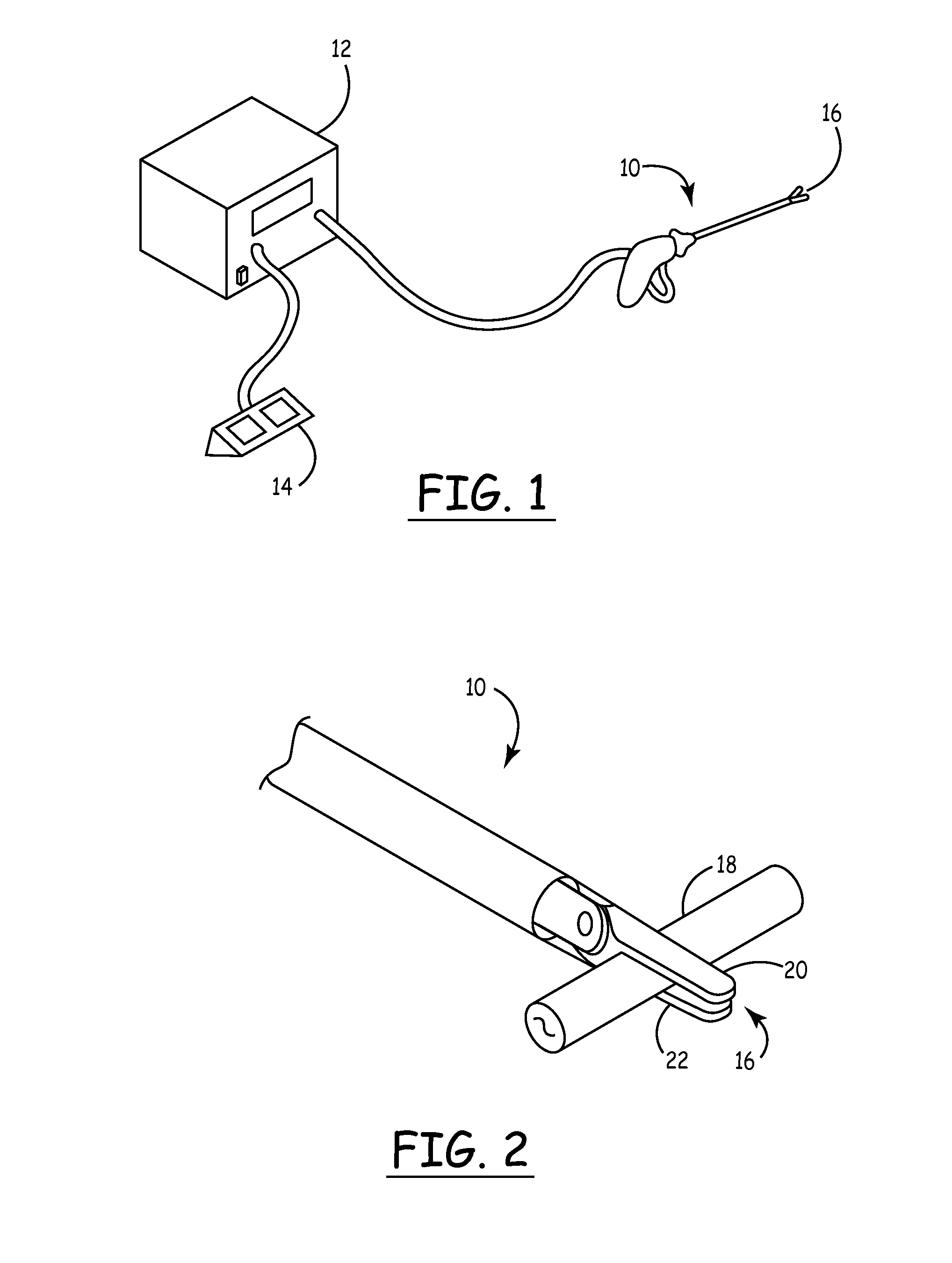
[0015]Referring now to the invention in more detail, in FIG. 1 there is shown a typical vessel sealing system with a device 10 connected to an electro-surgical generator 12 with energy being delivered to target tissue through the device's distal tip 16 by activating a footswitch 14. FIG. 2 illustrates further detail of a current sealing device 10 with a vessel 18 clamped between jaws 20 and 22 located at the distal tip 16 delivering the need pressure for sealing.

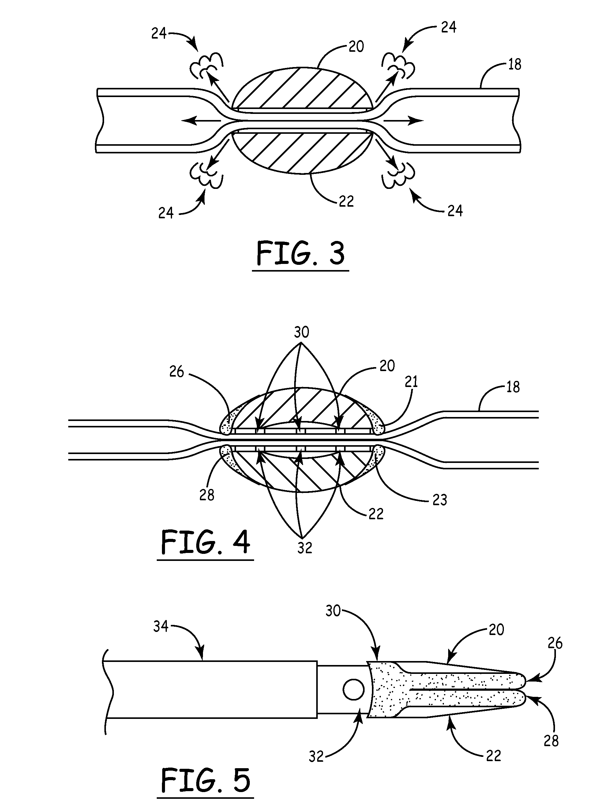
[0016]Referring now to more detail of current sealing devices, in FIG. 3 there is shown a cross-section of a vessel 18 grasped between jaws 20 and 22 with sufficient clamp force. To seal the vessel 18 RF energy is delivered between jaws 20 and 22 and through the tissue clamped between them. The flow of energy heats moisture in the tissue to the boiling point and it is through this heat and pressure that the vessel is permanently sealed. However, a large amount of heat escapes the seal zone along the outside jaw-tissue interf...


PUM


Abstract

An improved method and equipment for tissue / vessel sealing is disclosed for the sealing, coagulation and transection of tissue during surgical procedures. The improvement is accomplished through better management of heat and moisture present during tissue treatment by having tissue grasping surfaces comprised of an outer non-conducting region and an inner conductive region, and including channels in the jaw assembly to direct steam and moisture away from surrounding tissue. The outer region follows the perimeter each jaw, isolating the treatment zone and preventing steam and excess heat from leaving the tissue treatment zone, reducing thermal margins and unintended patient burns. The outer region also prevents surrounding moisture from affecting the treatment zone and allowing more consistent results.

Description

RELATED CASES[0001]This application claims priority to U.S. Provisional Application Ser. No. 61 / 068,246, filed Mar. 6, 2008, the content of which is herein incorporated by reference in its entirety.FIELD OF THE INVENTION[0002]The present invention is in the technical field of electro-surgical medical devices.[0003]More particularly, the present invention relates to devices used for the coagulation and sealing of vessels and tissue utilizing radio-frequency (RF) energy during open or laparoscopic surgical procedures.BACKGROUND OF THE INVENTION[0004]Devices used for the coagulation and sealing of vessels often utilizes heat generated by bipolar RF energy combined with clamping pressure to electrosurgically seal blood vessels and tissue as required during both open and laparoscopic surgical procedures. This process has become well accepted and replaces the use of sutures, clips and staples in many instances, reducing procedure time and cost.[0005]However, consistent performance is a co...

Claims


Application Information

Patent Timeline
Patent Type & Authority Applications(United States)
IPC IPC(8): A61B18/00
CPCA61B2018/00053A61B18/00A61B18/1445A61B2018/00083A61B2018/0063A61B2018/1452A61B2090/0427A61B2090/0436
Inventor LATTERELL, SCOTT T.
Owner SPINNAKER MEDICAL
Learn More