Magnetostrictive probe with inverted signal detection

a magnetic restriction and inverted signal technology, applied in liquid/fluent solid measurement, instruments, machines/engines, etc., can solve the problems of multiple signals in the waveguide, more baseline noise, and the approach often introduces level determination errors, etc., to achieve more accurate measurement

Active Publication Date: 2014-08-14
ASCENT-X LLC
View PDF6 Cites 7 Cited by
  • Summary
  • Abstract
  • Description
  • Claims
  • Application Information

AI Technical Summary

Benefits of technology

[0012]It is the aim of this invention to offer a solution to the mentioned signal detection problems, while offering a more accurate measurement by eliminating other factors that often affect the accuracy of the height measurement as well. As such, an improved magnetostrictive probe will result that will provide an accurate bottom reference for fuel and water levels. This new approach will thus allow for as true and accurate a measurement capability to be performed by this technology for tank level monitoring or for bottom referenced measurements.
[0015]There are many technical advantages associated with this strategic location of the sensing element at the foot of the probe. It eliminates the need to derive the tank's bottom level by assumption or some other schemes. The prior art approaches often introduce errors in level determination from a tank's bottom. This new technique also aims at removing the pickup element from the can where it is subjected to many undesirable influences such as temperature, vibrations, pickup movement due to expansion and contraction in the tube, the effect of magnetic risers, and electromagnetic influences. There are other benefits of this swap that have to do with shifting the waveguide away from the center of the tube where it will take advantage of stronger magnetic fields emanating from the permanent magnets located in the floats. With this kind of arrangement, the fields from a permanent magnet reaching the waveguide is stronger and therefore a stronger signal is obtained. This latter technique offers a twofold benefit: either using a lower current drive in the wire making the system safer in terms of intrinsic safety, or facilitates the construction of longer probes with reduced energy to drive the wire.

Problems solved by technology

This in turn produces multiple signals in the waveguide and as a result more baseline noise.
The prior art approaches often introduce errors in level determination from a tank's bottom.

Method used


Image

  • Magnetostrictive probe with inverted signal detection
  • Magnetostrictive probe with inverted signal detection
  • Magnetostrictive probe with inverted signal detection

Examples


Embodiment Construction

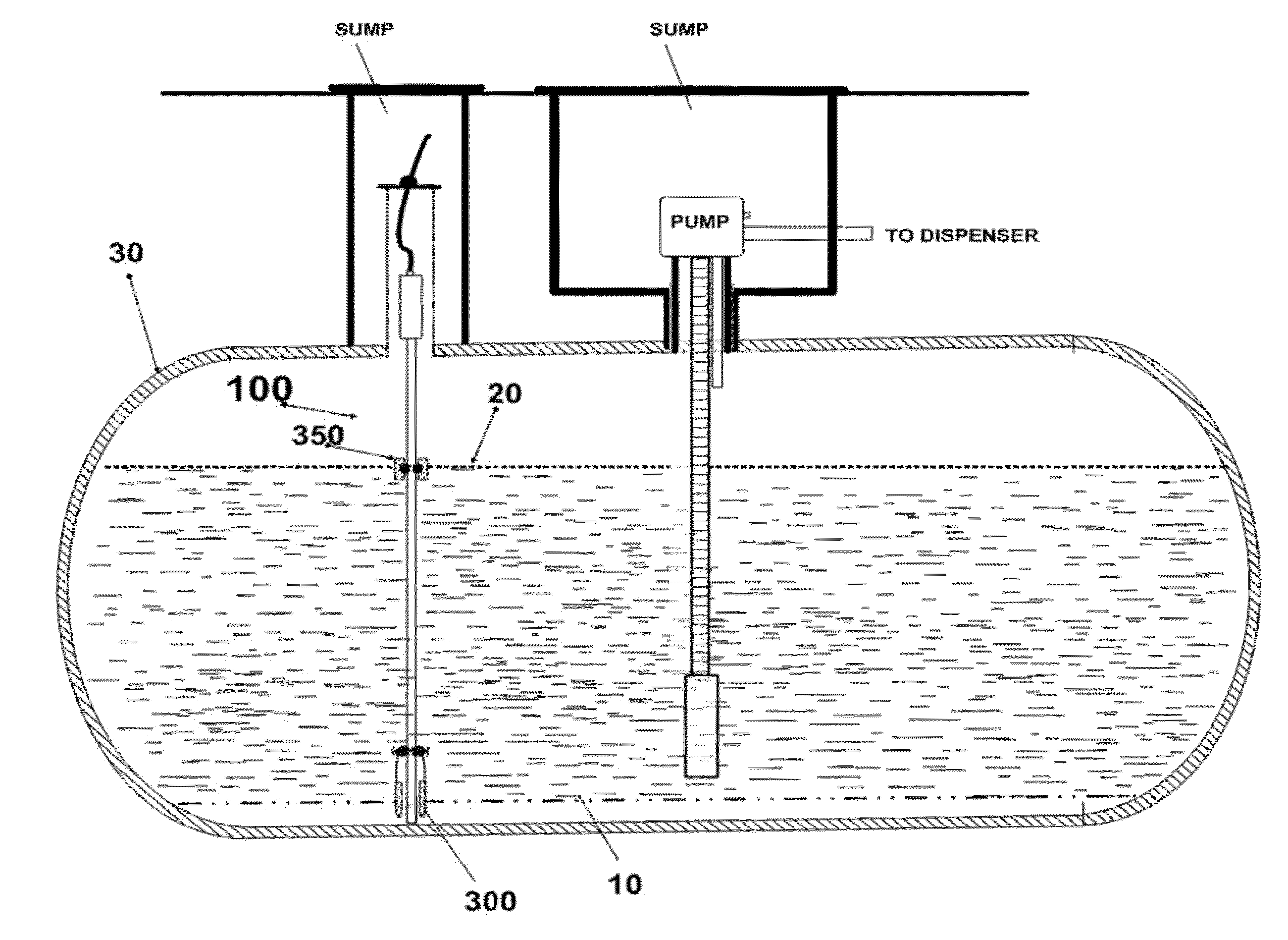
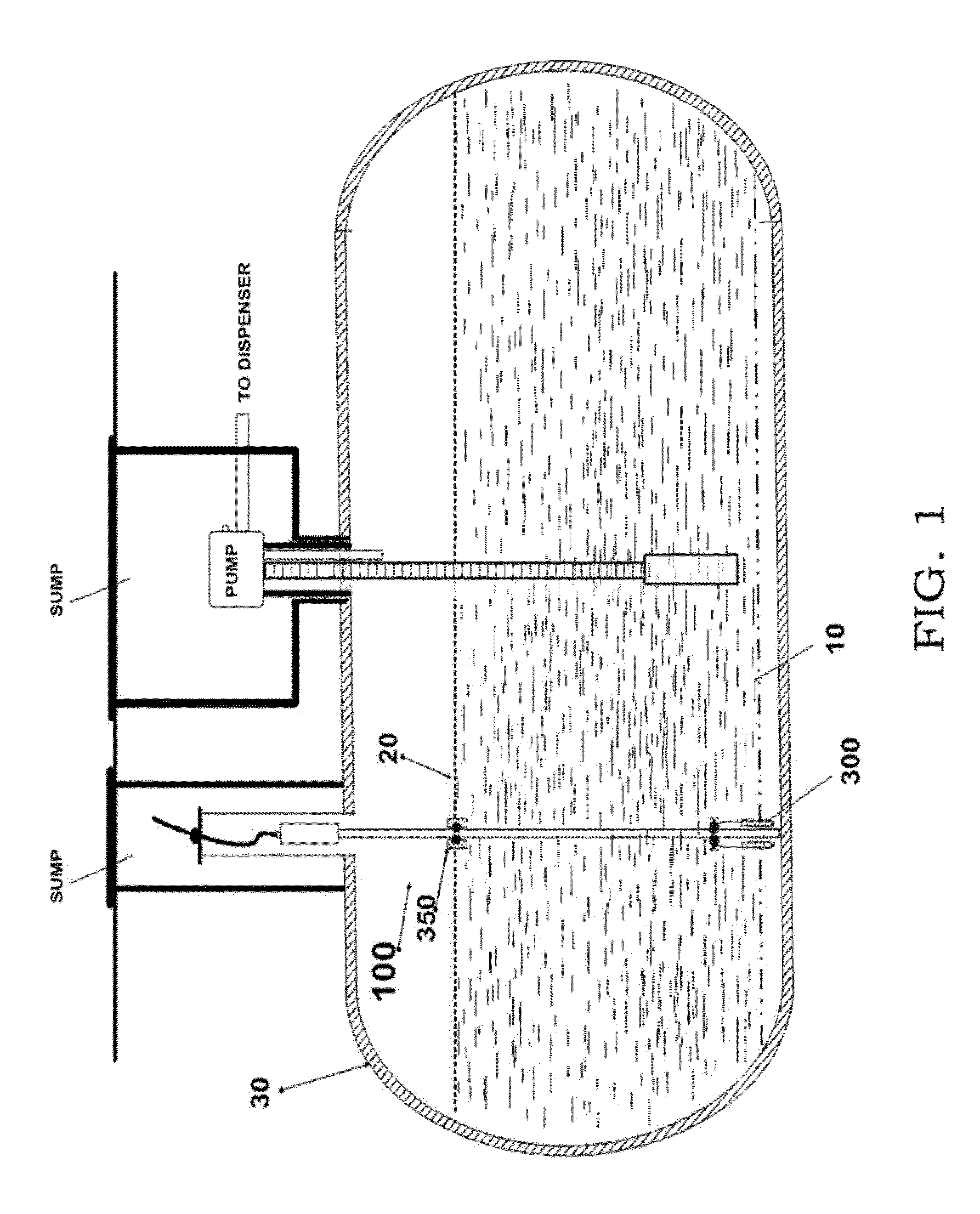
[0033]For over half a century since magnetostrictive technology has been in use for linear positioning devices, there has been many configurations intended to improve on its performance. From the early units that were used for data conversion from analog to digital as U.S. Pat. No. 2,995,736, referenced here in its entirety demonstrates, the technology has progressively been adapted to be used for many other applications involving linear positioning. For over half that time, magnetostrictive probes were adapted to be used for fuel level determination.

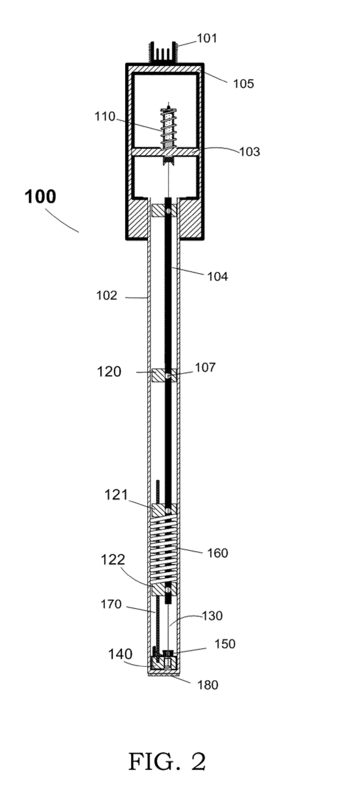
[0034]Due to constraints in tank entry ports, and the volatile nature of gasoline, restraints were maintained in introducing electrical equipment inside fuel tanks. With time, more knowledge was acquired. During that same time, electrical components were shrinking in size as well as power requirements. With this, it became possible to use miniaturized electrical elements in a probe.

[0035]The proposed adaptation of a magnetostrictive pro...


PUM


Abstract

The present discloses an alternate construction and method for a magnetostrictive probe intended to be used as a tank monitoring device. Height determination, either water or fuel, is referenced to an ultrasonic pickup assembly located inside the shaft at the foot of the probe. With this inverse approach, height measurement takes advantage of the relative geothermal stability of underground storage tanks, or the temperature stability offered by the thermal mass of the fuel, to facilitate a more accurate tank level determination. At that new location, the detection circuit gains the added benefits of being isolated from the effect of magnetic risers, large temperature swings and other undesirable phenomenon that often affect magnetostrictive probe measurements that are referenced to the canister. Aside from its primary use as referred to by this disclosure, this probe could be adapted for any application necessitating precise knowledge of height or distance measurement in relation to the foot of the probe without using a reference magnet.

Description

PRIORITY CLAIM[0001]The application described within claims the benefit of U.S. Provisional Patent Application Ser. No. 61 / 602,119, filed Feb. 23, 2012, which application is hereby incorporated by reference.FIELD OF THE INVENTION[0002]This present invention pertains to a linear positioning sensor intended for height and distance measurement. As used in this application, it is adapted for liquid level measurement particularly fuel and water level as found in fuel storage tanks. Other applications such as density and other fuel quality parameters may be ascertained from the information obtained from this device. Data coming from this sensor is relayed to a monitoring console where algorithms are used to further evaluate the different parameters inside of a tank.REFERENCES CITED2,995,736August 1961Tellerman5,017,867May 1991Dumais et al.5,076,100December 1991Hunter et al.5,258,707November 1993Begin et al.5,998,991December 1999John D. Begin.BACKGROUND OF INVENTION[0003]Many types of sens...

Claims


Application Information

Patent Timeline
Patent Type & Authority Applications(United States)
IPC IPC(8): G01B7/02G01F23/30
CPCG01B7/02G01F23/30G01F23/2963G01F23/72
Inventor PRINSTIL, AMBROISE
Owner ASCENT-X LLC
Why Eureka
Try Eureka