Method For Machining A Through-Hole In A Component And Machining Device For Implementing The Said Method

a technology of machining device and through-hole, which is applied in the direction of manufacturing tools, portable drilling machines, thread cutting auxiliaries, etc., can solve the problems of insatiable use of sheet clamp tool 26/b>, inability to achieve the desired surface finish of the hole, and inability to achieve the desired surface finish. , to achieve the effect of improving the surface finish of the hol

Active Publication Date: 2014-08-14
AIRBUS OPERATIONS (SAS)
View PDF9 Cites 8 Cited by
  • Summary
  • Abstract
  • Description
  • Claims
  • Application Information

AI Technical Summary

Benefits of technology

[0027]Advantageously, the rotational speed of the cutting tool about its rotation axis is greater than or equal to forty times the rotational speed of the first intermediate support about the first orbital rotation axis, and/or the rotational speed of the first intermediate support about the first orbital rotation axis is greater than or equal to forty times the rotational speed of the second intermediate support about the second orbital rotation axis. This feature makes it possible to improve the surface finish of the hole.
[0028]With one approach, set

Problems solved by technology

The use of a tool 26 of the sheet clamp type is not entirely satisfactory because the movements of the parts located on each side of the component need to be coordinated and these parts need to be posi

Method used


Image

  • Method For Machining A Through-Hole In A Component And Machining Device For Implementing The Said Method
  • Method For Machining A Through-Hole In A Component And Machining Device For Implementing The Said Method
  • Method For Machining A Through-Hole In A Component And Machining Device For Implementing The Said Method

Examples


Embodiment Construction

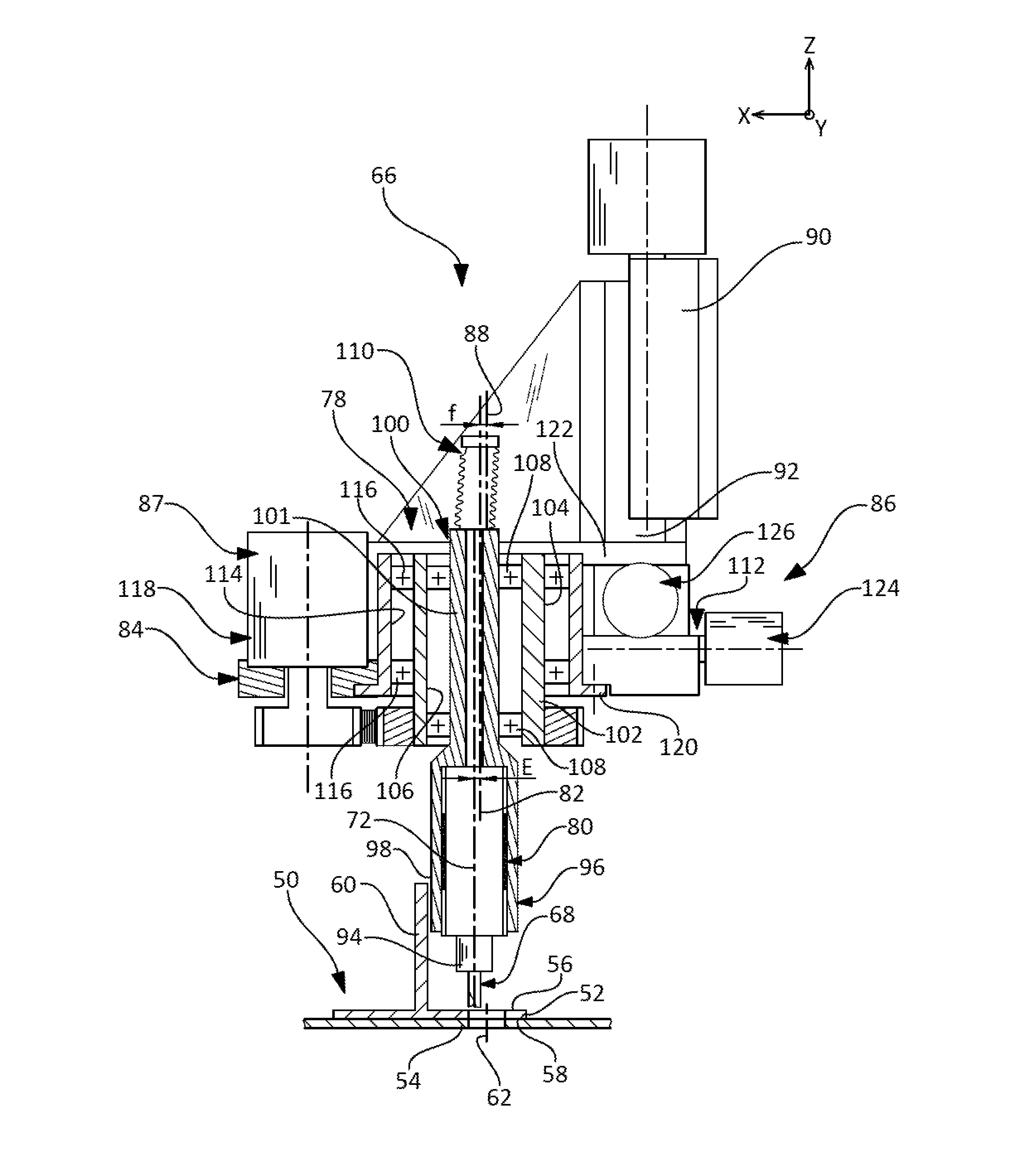
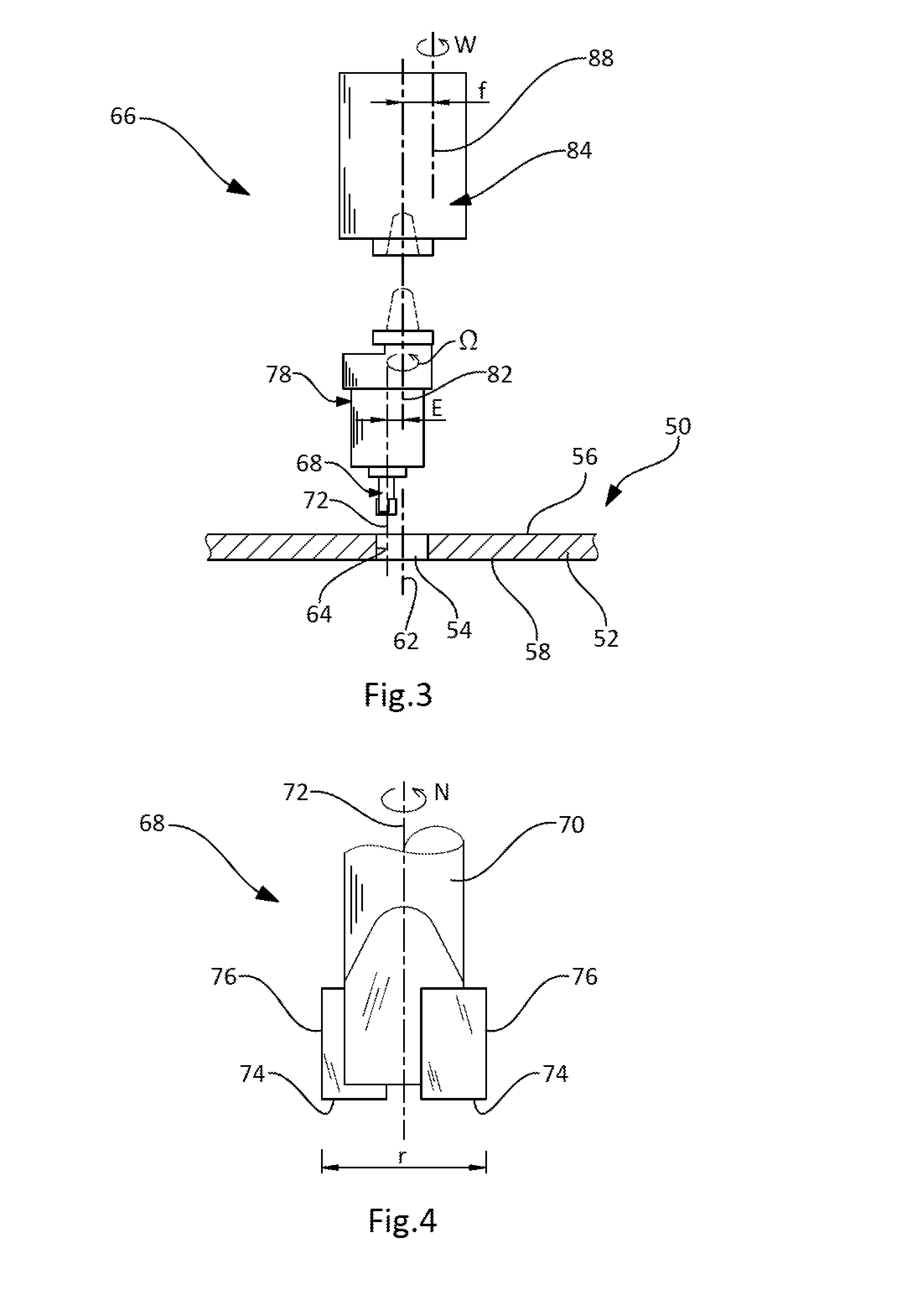
[0037]FIGS. 3 and 5 depict a component 50 which comprises a wall 52 in which a hole 54 is to be made, the hole 54 being open at a first surface 56 and a second surface 58. The component 50 may comprise a stiffener 60 (visible in FIG. 5) which extends from the first surface 56 near the hole 54.

[0038]In one application, the component 50 is made of composite material and comprises for example a stack of laps of fibres embedded in a resin matrix. Of course, the invention is not restricted to this application and may be suitable for metal components or components made of some other material.

[0039]By way of example, the component 50 forms part of an aircraft, such as a fuselage frame, stringers, fuselage panels, for example.

[0040]The hole 54 is defined by an axis 62, generally perpendicular to the first surface 56, and by a surface of revolution 64 about the said axis 62 and which may be cylindrical. However, the invention is not restricted to this geometry. Thus, the hole may have a coun...


PUM

PropertyMeasurementUnit
Speedaaaaaaaaaa
Radiusaaaaaaaaaa

Abstract

A method for machining a through-hole in a wall of a component, includes setting in rotation on itself a cutting tool about a rotation axis and setting the rotation axis of the tool in rotation about a first orbital rotation axis parallel to, and eccentric by an eccentricity E with respect to, the rotation axis of the tool. The method further includes setting the first orbital rotation axis in rotation, over at least one revolution, about a second orbital rotation axis parallel to, and eccentric by an amount f with respect to, the first orbital rotation axis, the eccentricity being fixed. This configuration makes it possible to balance the elements located between the rotation axis of the tool and the first orbital rotation axis, so that the rotation axis can thus be set in rotation about the first orbital rotation axis at high rotational speeds that contribute toward increasing productivity.

Description

[0001]The present invention relates to a method for machining a through-hole in a component and to a machining device used for implementing it, the machining method being more particularly suited to components made of composite material.BACKGROUND OF THE INVENTION[0002]In the aeronautical field, many aircraft components are made of composite material in order to reduce the onboard mass and thereby the energy consumption of the aircraft. By way of example, the orbital frames of the fuselage, the stringers and the fuselage panels may be made of composite material.[0003]Some of these composite components need to be machined in order to create, amongst other things, through-holes which are used notably for joining the components together.[0004]A first approach, illustrated in FIG. 1, might be to make a through-hole 10 in a component 12 by drilling, using a drill bit 14 secured to a tool holder 16 which pivots about a rotation axis 18 with respect to a machine tool 20. With this approach...

Claims


Application Information

Patent Timeline
IPC IPC(8): B23B35/00B23B39/16
CPCB23B39/16B23B35/00B23C3/02B23C2215/04B23C2220/52B23C2226/27Y10T408/03Y10T408/65Y10T409/303808Y10T409/307616
Inventor DE MATTIA, DENISBATARD, GILLES
Owner AIRBUS OPERATIONS (SAS)
Why Eureka
Try Eureka