

Method of manufacturing light emitting element
- Summary
- Abstract
- Description
- Claims
- Application Information
AI Technical Summary
Benefits of technology
Problems solved by technology
Method used
Image

Examples
embodiment 1
Variation 1
[0104]As shown in FIGS. 10A and 10B, in a light emitting element 10A manufactured according to a method of manufacturing a light emitting element according to Variation 1 of Embodiment 1, the substrate 2 is removed and the lower surface (main light emitting surface) and the side surfaces are covered with a wavelength converting member 8 with respect to the light emitting element 10 shown in FIGS. 1A and 1B. Further, the light emitting element 10A does not have the bonding layers 91, 92, so that at the time of bonding on the wiring substrate (not shown), a bonding member such as a solder is used. In the light emitting element 10A, at the peripheral portion in a plan view, the insulating member 6A is disposed inner side with respect to the region where the p-type semiconductor layer 13 and the active layer 12 of the semiconductor structure 1 are not removed (except for n-side contact region). Accordingly, in the light emitting element 10A, light emitted from the semiconduct...
first embodiment
Second Variation
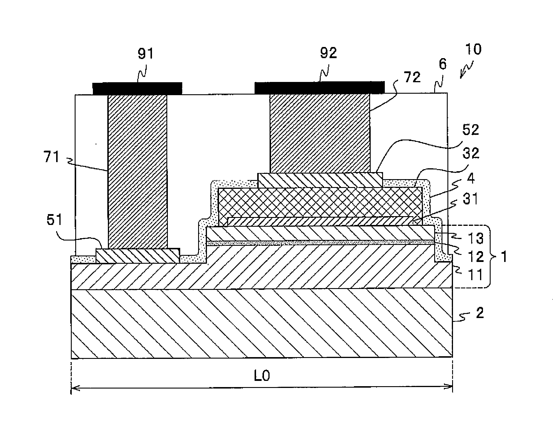
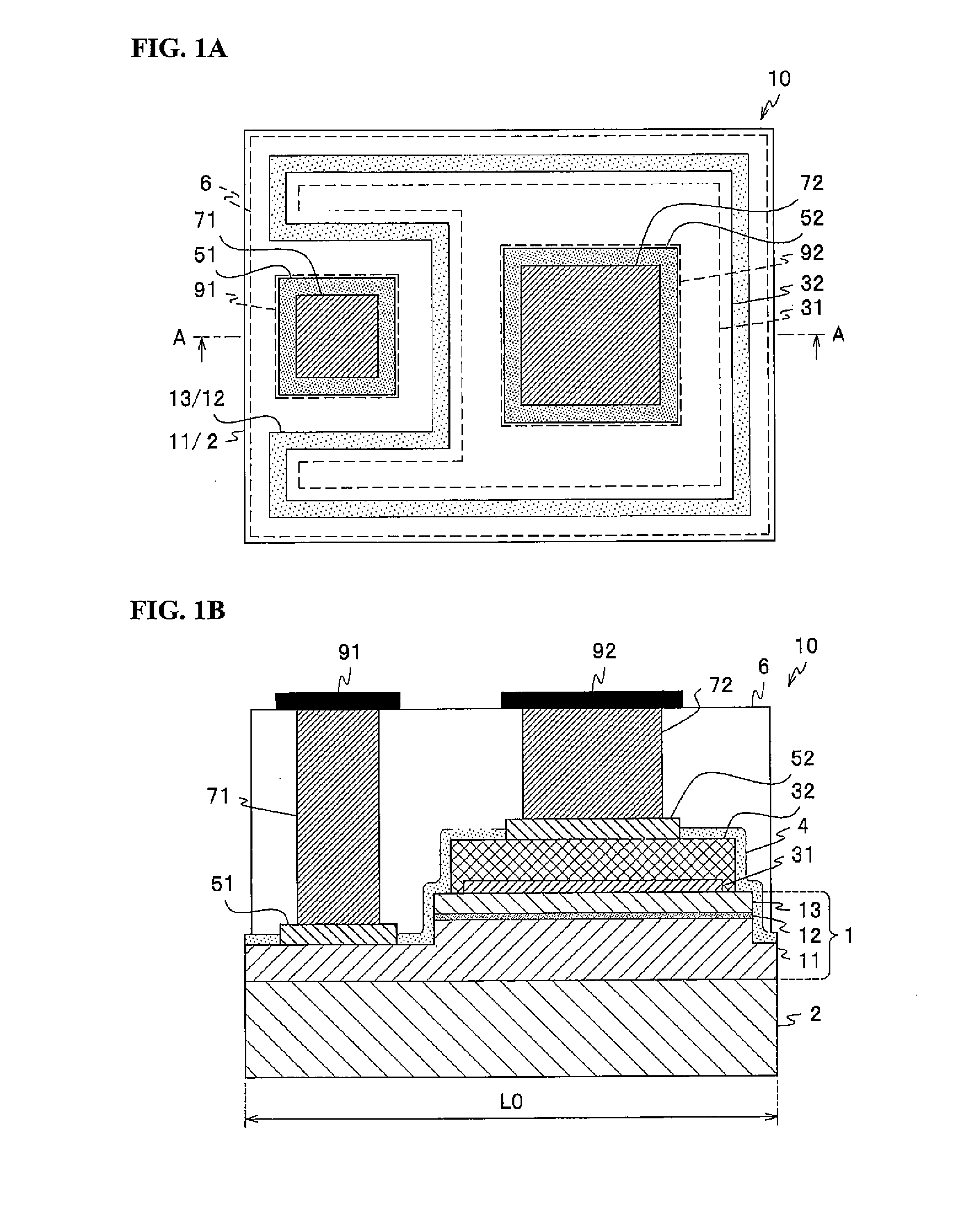
[0119]As shown in FIG. 13A, the light emitting element 10B fabricated according to a method of manufacturing a light emitting element according to Variation 2 has an approximately square shape in a plan view and has a symmetrical structure. For this reason, in FIG. 13A, the substrate 2B to the protective layer 4B are shown on the left side of the center line, and the pad electrodes 51B, 52B are shown, with the bumps 71B, 72B and the insulating member 6 shown by their outlines, on the right side of the center line. The light emitting element 10B has a similar structure as the light emitting element 10 (see FIG. 1) of Embodiment 1 except that the light emitting element 10B does not have the bonding layers on the Bumps 71B, 72B respectively, in a similar manner as the light emitting element 10A (see FIG. 10) of Variation 1 described above, and that the components of the light emitting element 10B have different shapes than that of the light emitting element 10.
[0120]In ...
second embodiment
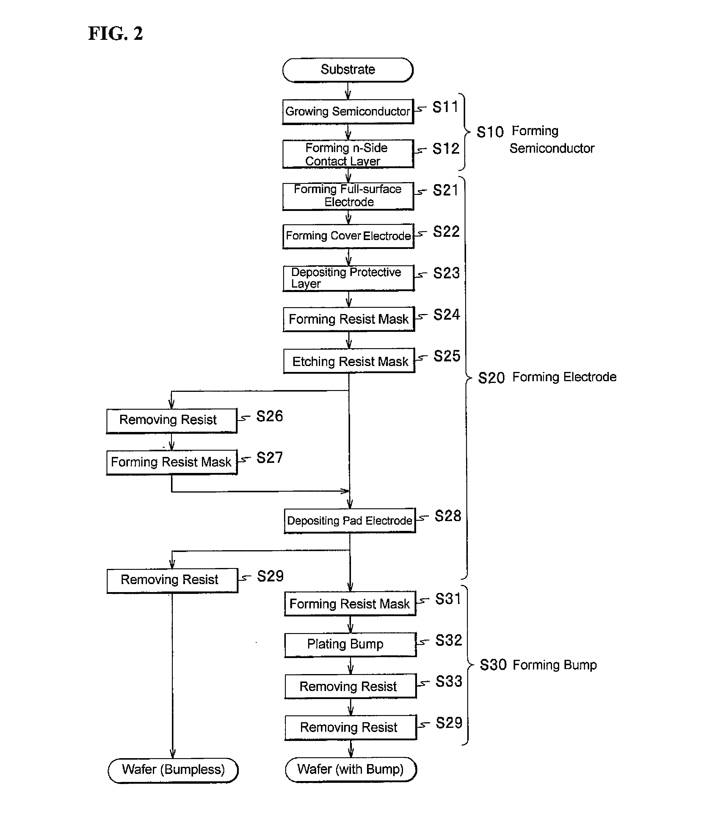
[0131]In a method of manufacturing a light emitting element according to Embodiment 1 and the variations of Embodiment 1, forming bumps on the wafer then grinding the bumps with the insulating member which cover the surroundings of the bumps, to facilitate electric connection to outside (wiring substrate) at the flat upper surfaces, but a structure in which the bumps are not formed and electrical connection to outside is facilitated with the flat upper surfaces (bumpless structure) can also be employed. Next, referring to FIG. 14 to FIG. 17E, and FIG. 2, a method of manufacturing a light emitting element according to Embodiment 2 of the present invention and a light emitting element obtained by the method will be described below. In the following, identical members or members of same quality as in Embodiment and the variations of Embodiment 1 are assigned the same reference numerals and description thereof will be appropriately omitted.
[0132]As shown in FIG. 14, in the light emittin...
PUM
 Abstract
Description
Claims
Application Information