High-throughput graphene printing and selective transfer using a localized laser heating technique

a laser heating and high-throughput technology, applied in the field of nanofabrication of graphene patterns, can solve the problems of long processing time, low yield, high processing cost, etc., and achieve the effect of facilitating high-speed and high-throughput graphene pattern printing

Active Publication Date: 2014-08-21
STEVENS INSTITUTE OF TECHNOLOGY
View PDF0 Cites 18 Cited by
  • Summary
  • Abstract
  • Description
  • Claims
  • Application Information

AI Technical Summary

Benefits of technology

[0007]Embodiments of the present invention provide a technique that facilitates high-speed and high-throughput graphene pattern printing using localized heat sources, such as, but not limited to, lasers. In an embodiment of the present invention, large-area graphene is applied to a thermal release tape, and a substrate is placed in contact with the large-area graphene. In an embodiment of the present invention, a localized heat source, such as a laser beam, locally heats the thermal release tape such that the locally-heated area of the tape loses its adhesive properties, and the graphene on that locally-heated area of the thermal release tape is selectively transferred onto the substrate.

Problems solved by technology

Some of the disadvantages of these processes include high processing cost, long processing time, low yield, and unwanted doping of graphene.
In addition, these processes are not compatible with flexible polymer substrates.
Techniques where graphene patterns are printed using graphene ink overcome these disadvantages, but do not provide a continuous printed pattern.
Hence, such techniques have limited use in applications such as nanoelectronics where the continuity of the graphene pattern may be critical to the performance of the device.
The element indium is becoming increasingly rare and expensive.
ITO is also brittle, which heightens the risk of a screen cracking when a smart phone is dropped, and further rules ITO out as the basis for flexible displays.
Efforts to make transparent conducting films from large-area graphene, however, have been hampered by the lack of efficient methods for the synthesis, patterning and transfer of graphene at the scale and quality required for applications in high performance nanoelectronics.
The fabrication of the graphene-based active component, however, requires complex, expensive and time-consuming processes using conventional lithography techniques.

Method used


Image

  • High-throughput graphene printing and selective transfer using a localized laser heating technique
  • High-throughput graphene printing and selective transfer using a localized laser heating technique

Examples


experimental verification

[0016]The following experiments (i.e., Experiment 1 and Experiment 2) have been conducted, and verify the utility of the present invention. Good uniform transfer of large-area graphene on the targeted substrate using a roller press was demonstrated (Experiment 1), and local heating of the thermal release tape was observed to consistently transfer graphene only in the locally heated areas (Experiment 2). The results of Experiments 1 and 2 are summarized below.

experiment 1

Method

[0017]Large-area graphene transfer onto a substrate was demonstrated using a roller-press apparatus. Silicone rollers were used to press multiple layers of large-area graphene adhered to a thermal release tape (thermal release tape 3195MS, Semiconductor Equipment Corporation) against a film of PET polymer at high temperatures (i.e., temperatures equal to or greater than about 100° C.), and a uniform pressure in the range of about 5 psi to about 10 psi. At high temperatures, the thermal release tape lost its adhesive properties and the graphene layer was transferred onto the PET substrate. Three temperatures were tested (i.e., 100° C., 120° C., and 150° C.). Care was taken to ensure that the PET film did not soften during the transfer process.

[0018]Homogeneous transfer of large-area graphene was observed at all three temperatures. The best transfer, based on the amount of large-area graphene transferred to the substrate and the uniformity of the large-area graphene transferred,...

experiment 2

g and Transfer Method

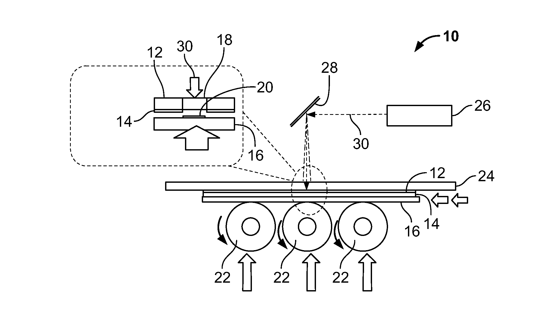
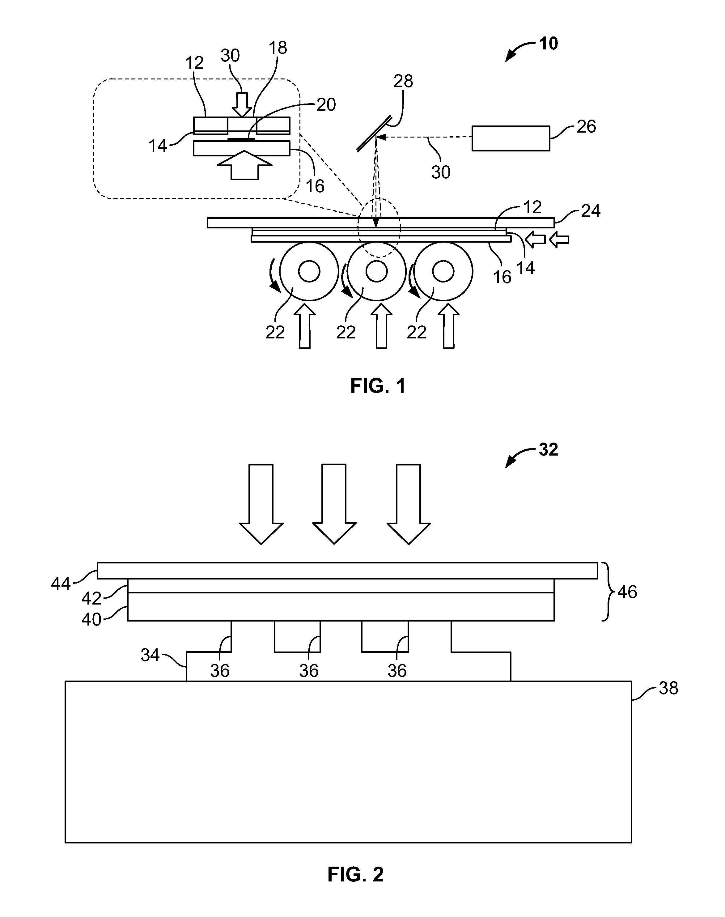
[0020]The feasibility of local graphene transfer from large-area graphene to a substrate was demonstrated by locally heating thermal release tape having large-area graphene adhered thereto. FIG. 2 is a schematic illustration of the experimental set-up 32 used for this experiment. Turning to FIG. 2 for reference, a silicon oxide wafer 34 with a pattern of 1 mm-diameter circular pedestals 36 was placed on a hot plate 38 and heated to 150° C. A thermal release tape 40 (thermal release tape 3195MS, Semiconductor Equipment Corporation) having large-area graphene 42 adhered thereto was placed with the graphene 42 in contact with a silicon substrate 44. The resulting stack 46 of substrate-graphene-tape was then placed carefully onto the heated circular pedestals 36 with the thermal release tape 40 in contact with the pedestals 36. Downward pressure was applied to the stack 46 using weights (not shown) placed on top of the silicon substrate 44, thereby pressing the ther...


PUM

PropertyMeasurementUnit
temperatureaaaaaaaaaa
temperaturesaaaaaaaaaa

Abstract

A method of high-throughput printing and selective transfer of graphene onto a substrate includes the steps of: providing a thermal release tape having graphene adhered thereto; placing a substrate onto the graphene; pressing the thermal tape and the graphene against the substrate at a uniformly-distributed pressure; heating localized portions of the thermal tape and graphene using a localized heat source, thereby diminishing the adhesive properties of the thermal release tape in the localized portions and transferring graphene from said localized portions to the substrate; and separating the thermal release tape from the substrate. The method may include the further step of moving the localized heat source to selected positions on the thermal release tape during the heating step, thereby forming a pattern of heated portions. The method may use a laser beam as the localized heat source, movement of the laser beam being performed by a computer-controlled deflectable mirror.

Description

CROSS-REFERENCE TO RELATED APPLICATION[0001]The present application claims the benefit of U.S. Provisional Patent Application No. 61 / 766,956, filed on Feb. 20, 2013, which is incorporated by reference herein in its entirety.FIELD OF THE INVENTION[0002]The present invention relates to the field of nanofabrication of graphene patterns, in particular, utilizing a localized heat source, such as a laser beam, for localized graphene transfer from large-area graphene.BACKGROUND OF THE INVENTION[0003]The capability to produce high-quality graphene on a large scale has become a key factor in commercializing graphene-based technologies. Graphene exhibits extraordinary properties which can be utilized for many applications in various fields of science and engineering. A reliable, fast and economical fabrication technique is necessary for the commercialization of graphene-based products. Current techniques for producing graphene devices involve the use of photolithography or e-beam lithography ...

Claims


Application Information

Patent Timeline
Patent Type & Authority Applications(United States)
IPC IPC(8): B32B37/00
CPCB32B37/025C01B32/186Y10T156/1705H01L29/66015
Inventor PATIL, VIKRAMKIM, YOUN-SUKUMAR, KITUYANG, EUI-HYEOK
Owner STEVENS INSTITUTE OF TECHNOLOGY
Why Eureka
Try Eureka