spectrometer

a spectrometer and compact technology, applied in the field of spectrometers, can solve the problem of extremely compact spectrometers, and achieve the effect of good optical performance parameters and low outlay

Inactive Publication Date: 2014-08-21
CARL ZEISS MICROSCOPY GMBH
View PDF4 Cites 3 Cited by
  • Summary
  • Abstract
  • Description
  • Claims
  • Application Information

AI Technical Summary

Benefits of technology

[0004]Starting from here, the object of the invention is to provide a spectrometer which is compact, requires a low outlay for adjustment and assembly and has good optical performance parameters.

Problems solved by technology

Furthermore, the spectrometer is extremely compact as all optically effective surfaces are formed on the transparent body or its front and rear side.

Method used


Image

  • spectrometer
  • spectrometer
  • spectrometer

Examples


Embodiment Construction

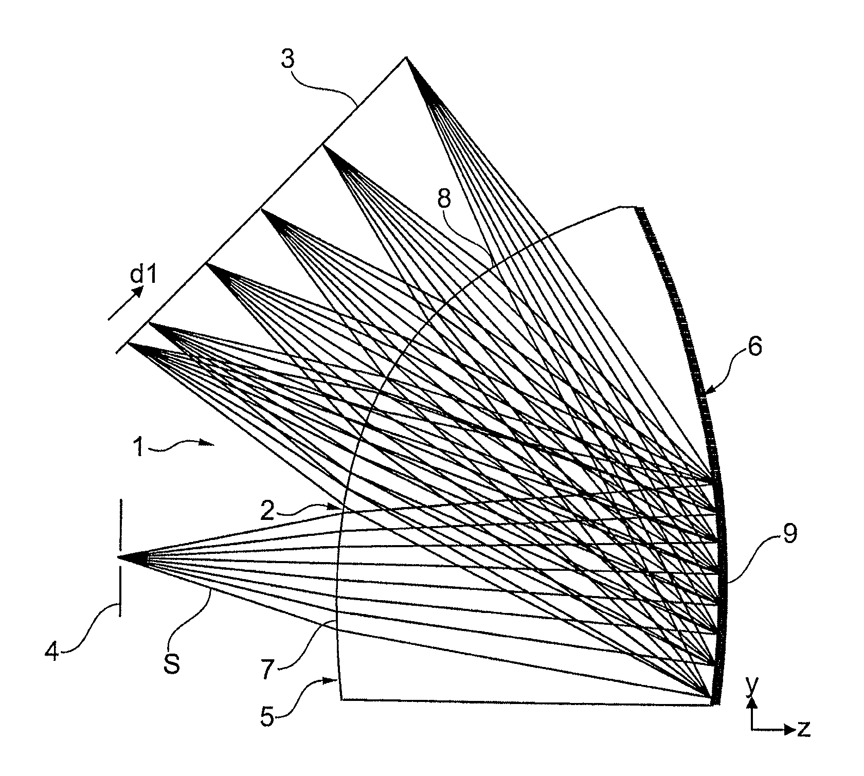
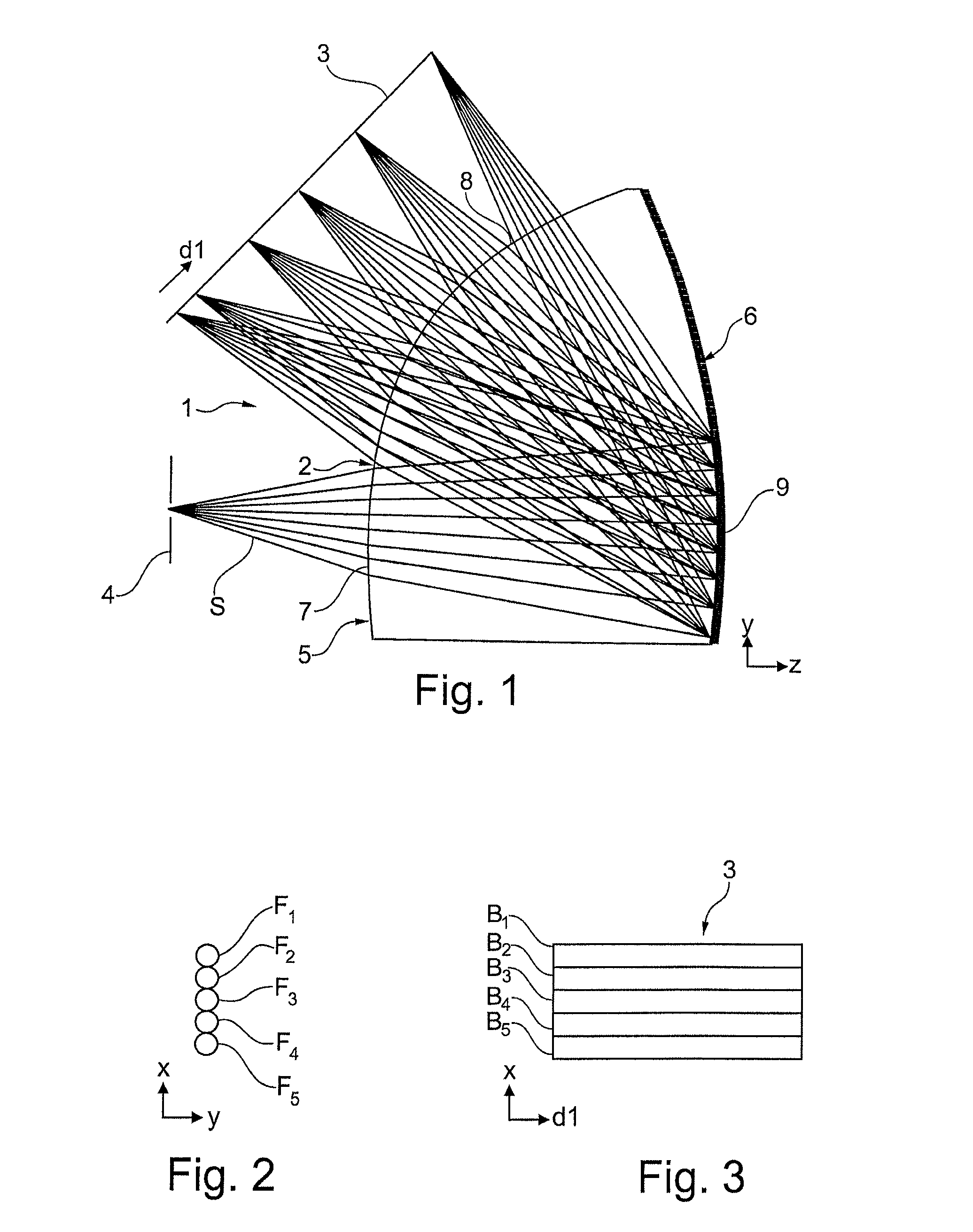
[0026]In the embodiment shown in FIG. 1, the spectrometer 1 according to the invention comprises a monolithic transparent body 2, a detector 3 and an entrance slit 4.

[0027]The body 2 has a front side 5 and a rear side 6, wherein an entry area 7 and an exit area 8 are formed on the front side 5 and a reflection grating 9 is formed on the rear side 6.

[0028]The rear side 6 is formed spherically curved and the grating lines of the reflection grating 9 extend perpendicular to the plane of drawing of FIG. 1, wherein the reflection grating is formed as a blazed diffraction grating (the grating lines in a sectional plane parallel to the plane of drawing of FIG. 1 thus have a saw-tooth profile).

[0029]As can be seen from FIG. 1, a beam S, coming from the entrance slit 4, enters the transparent body 2 via the entry area 7 and runs as far as the reflection grating 9. At the reflection grating 9 the beam S is reflected towards the exit area 8, wherein the reflected beam S exits the body 2 via th...


PUM


Abstract

A spectrometer with a detector and a transparent body which has an entry area and an exit area on a front side of the body and a reflection grating on a rear side of the body. A beam entering the body via the entry area is reflected at the reflection grating to the exit area and in the process is spectrally split and passes through the exit area and impinges on the detector. The rear side is curved at least in the region of the reflection grating in such a way that the beam is focused in the horizontal and vertical planes when it is reflected at the reflection grating.

Description

PRIORITY CLAIM[0001]The present application is a National Phase entry of PCT Application No. PCT / EP2012 / 064409, filed Jul. 23, 2012, which claims priority from German Application Number 102011080276.2, filed Aug. 2, 2011, the disclosures of which are hereby incorporated by reference herein in their entirety.FIELD OF THE INVENTION[0002]The present invention relates to a spectrometer, in particular a compact spectrometer.BACKGROUND OF THE INVENTION[0003]Spectrometers are used in a large number of applications, from routine analysis in the laboratory, through process measurement technology, to quality assurance in manufacturing. Many of these spectrometers, however, have the disadvantage that they consist of a large number of optical and mechanical components which require a high outlay for assembly and adjustment, with the result that cost-effective manufacture is often not possible.SUMMARY OF THE INVENTION[0004]Starting from here, the object of the invention is to provide a spectrome...

Claims


Application Information

Patent Timeline
Patent Type & Authority Applications(United States)
IPC IPC(8): G01J3/02G01J3/18
CPCG01J3/18G01J3/0256G01J3/0205G01J3/0208G01J3/0259
Inventor DOBSCHAL, HANS-JUERGENMUELLER, JOCHEN
Owner CARL ZEISS MICROSCOPY GMBH
Why Eureka
Try Eureka