Transmission device and transmission method
- Summary
- Abstract
- Description
- Claims
- Application Information
AI Technical Summary
Benefits of technology
Problems solved by technology
Method used
Image

Examples
embodiment 1
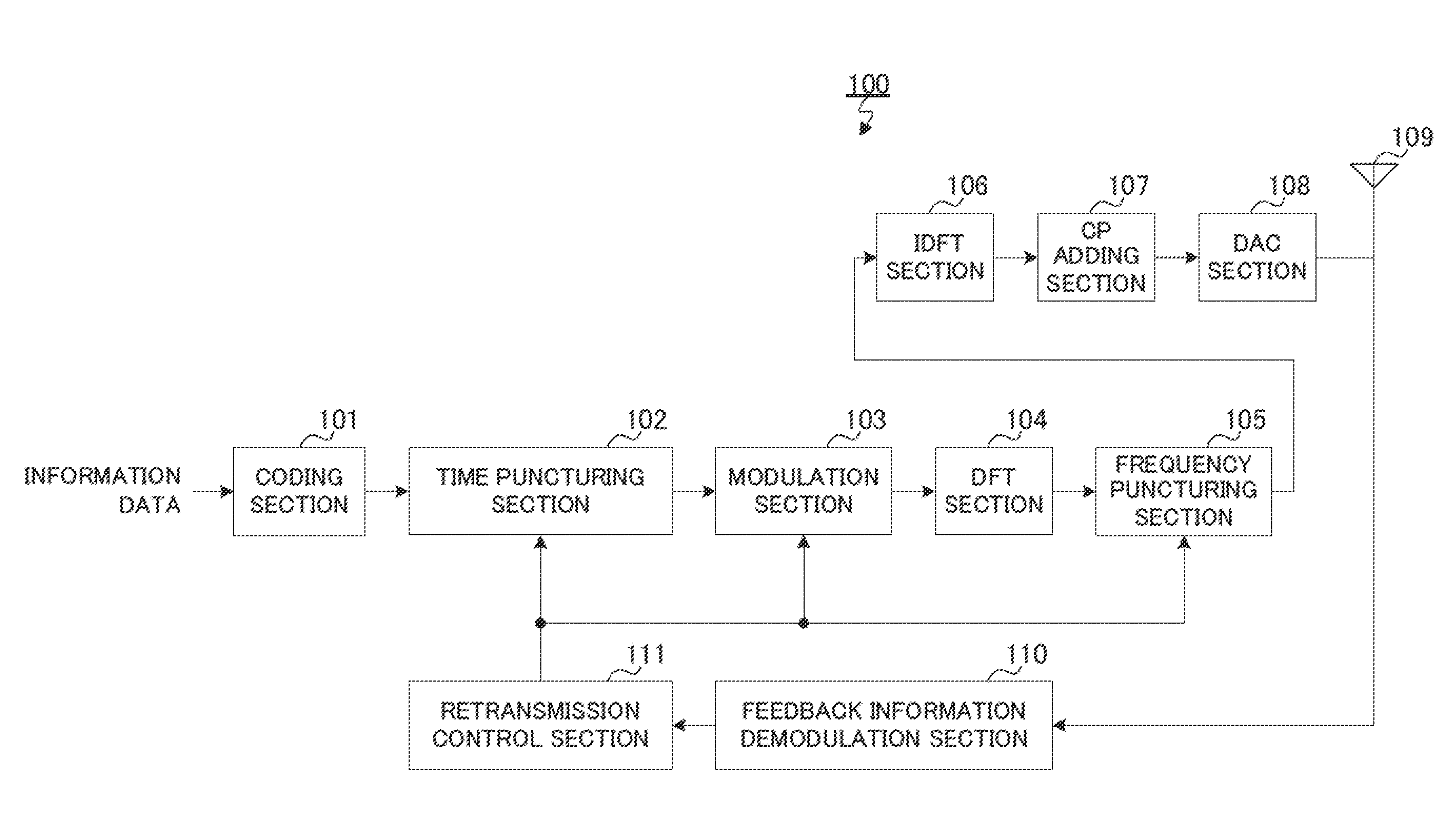
[0040]FIG. 3 illustrates major components of transmission apparatus 100 according to the present embodiment. Transmission apparatus 100 shown in FIG. 3 transmits bits of encoded data in sequence on a per transmission basis, the encoded data including systematic bits and parity bits, and performs the frequency puncturing to puncture data to be punctured, in which data the bits are convoluted into a plurality of symbols in the frequency domain, on a per symbol basis. In transmission apparatus 100, time puncturing section 102 extracts data on a per transmission basis from the encoded data, and frequency puncturing section 105 performs the frequency puncturing depending on a ratio between the systematic bits and the parity bits included in the data.
[0041]FIG. 4 is a block diagram that illustrates a configuration of the transmission apparatus according to the present embodiment. Transmission apparatus 100 shown in FIG. 4 transmits bits of encoded data, which include systematic bits and p...
transmission example 1
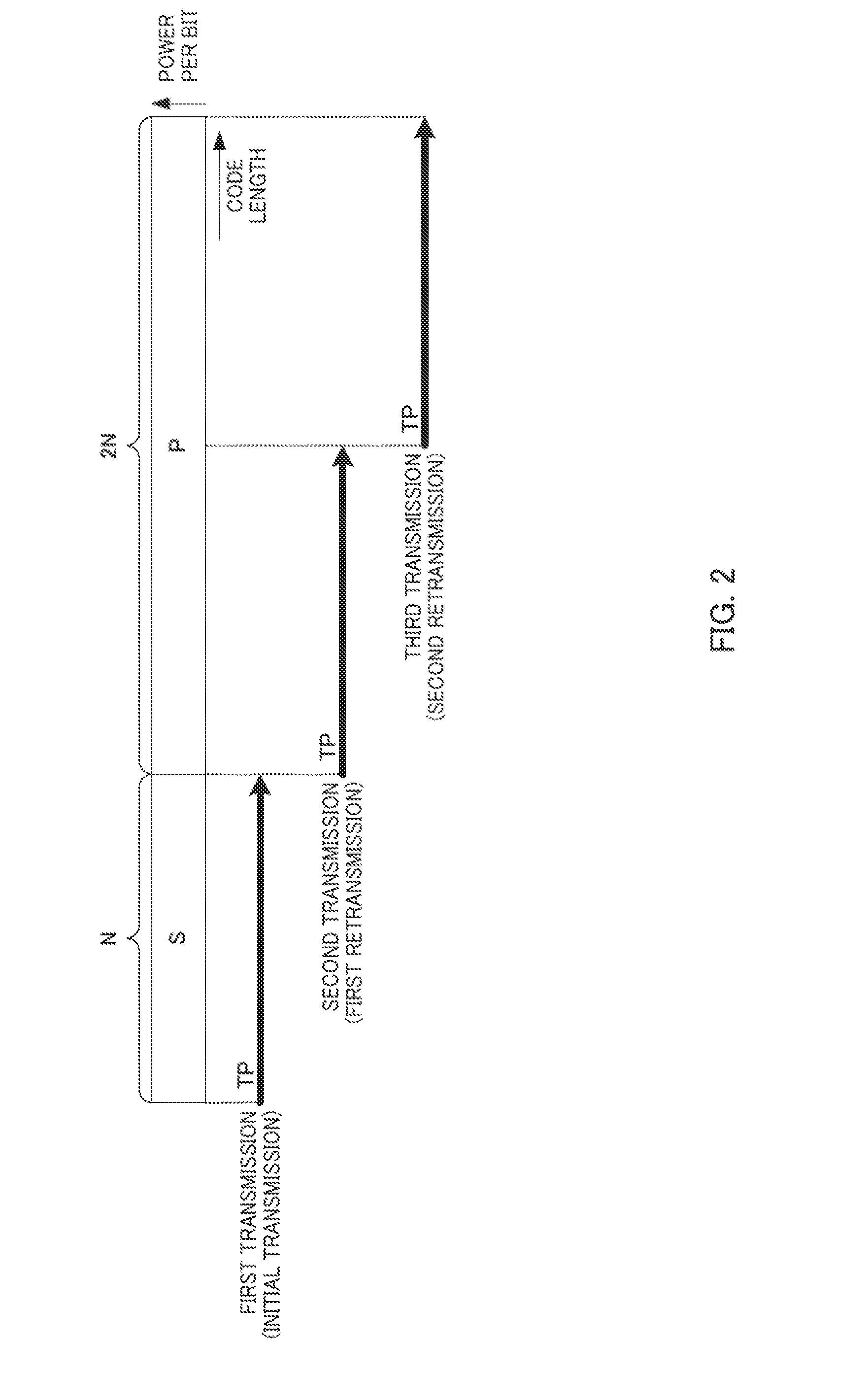
[0076]FIG. 8 illustrates an example of the transmission process in transmission apparatus 100 in transmission example 1. As shown in FIG. 8, the number of systematic bits S is N, and the number of parity bits P is 2N (and thus coding section 101 has a code rate of ⅓).
[0077]Retransmission control section 111 of transmission apparatus 100 provides time puncturing information (positions of bits to be transmitted and the number of bits to be transmitted) to time puncturing section 102 every time a transmission occurs. Based on the time puncturing information, for example, as shown in FIG. 8, time puncturing section 102 extracts the systematic bits S by the time puncturing in the first transmission (in the initial transmission), and extracts a portion of the parity bits P by the time puncturing in the second transmission (in the first retransmission) or in the third transmission (in the second retransmission).
[0078]Retransmission control section 111 also indicates to frequency puncturing...
transmission example 2
[0088]In contrast to transmission example 1 (FIG. 8) where only the systematic bits are transmitted in the initial transmission, in transmission example 2, both the systematic bits and the parity bits are transmitted in the initial transmission.
[0089]FIG. 10 illustrates an example of the transmission process in transmission apparatus 100 in transmission example 2. As shown in FIG. 10, the number of systematic bits S is N, and the number of parity bits P is 2N (and thus coding section 101 has a code rate of ⅓). The term “TP rate” stands for a time puncturing rate and is represented, for example, by Rt in the following expression 5:
(Expression5)Rt=NumberofBitsOutputfromTimePuncturingSectionNumberofBitsInputtoTimePuncturingSection[5]
[0090]FIG. 11 shows the number of bits to be transmitted (the number of bits that are actually transmitted, i.e., the number of bits that are extracted from a CB by the time puncturing), the frequency puncturing rate Rf, the effective number of bits to be t...
PUM
 Abstract
Description
Claims
Application Information
 - R&D
- Intellectual Property
- Life Sciences
- Materials
- Tech Scout
- Unparalleled Data Quality
- Higher Quality Content
- 60% Fewer Hallucinations
Browse by: Latest US Patents, China's latest patents, Technical Efficacy Thesaurus, Application Domain, Technology Topic, Popular Technical Reports.
© 2025 PatSnap. All rights reserved.Legal|Privacy policy|Modern Slavery Act Transparency Statement|Sitemap|About US| Contact US: help@patsnap.com