Aircraft inerting system

a technology of inert gas and aircraft, which is applied in the direction of water supply installation, functional valve type, transportation and packaging, etc., can solve the problem of aircraft resources consumption, achieve the effect of reducing the volume of inert gas required, reducing the volume of fuel tank ullage, and optimizing the use of energy resources on-board the aircra

Active Publication Date: 2014-08-28
AIRBUS OPERATIONS LTD +1
View PDF2 Cites 19 Cited by
  • Summary
  • Abstract
  • Description
  • Claims
  • Application Information

AI Technical Summary

Benefits of technology

[0008]The invention is advantageous in that by actively controlling the flow rate of inert gas being introduced into the fuel tank, use of energy resources on-board the aircraft can be optimised. As the fuel in the fuel tank is consumed (by the aircraft engines) the fuel tank ullage volume will increase. As the ambient air pressure increases (e.g. during descent from a higher altitude) there would ordinarily be a net inflow of ambient air into the vented fuel tank. By substantially matching the ambient air ingestion—due to pressure changes—and ullage volume expansion—due to fuel burn—with the amount of inert gas supplied to the fuel tank, an optimised inerting solution can be realised. Compared with an inerting solution where an excess of inert gas is introduced into the fuel tank to maintain the UGOF below stated limits based upon worst case scenario estimations, the volume of inert gas required will be reduced.
[0009]With any inerting system, whether this be an ASM or a hydrogen fuel cell producing ODA as a bi-product of electrical power generation, optimising the supply of inert gas to the fuel tank will minimise the drain on energy resources. In the case of an AS

Problems solved by technology

Reducing the temperature and humidity is a known technology however it consumes aircraft resources, in particular cre

Method used


Image

  • Aircraft inerting system
  • Aircraft inerting system
  • Aircraft inerting system

Examples


Embodiment Construction

)

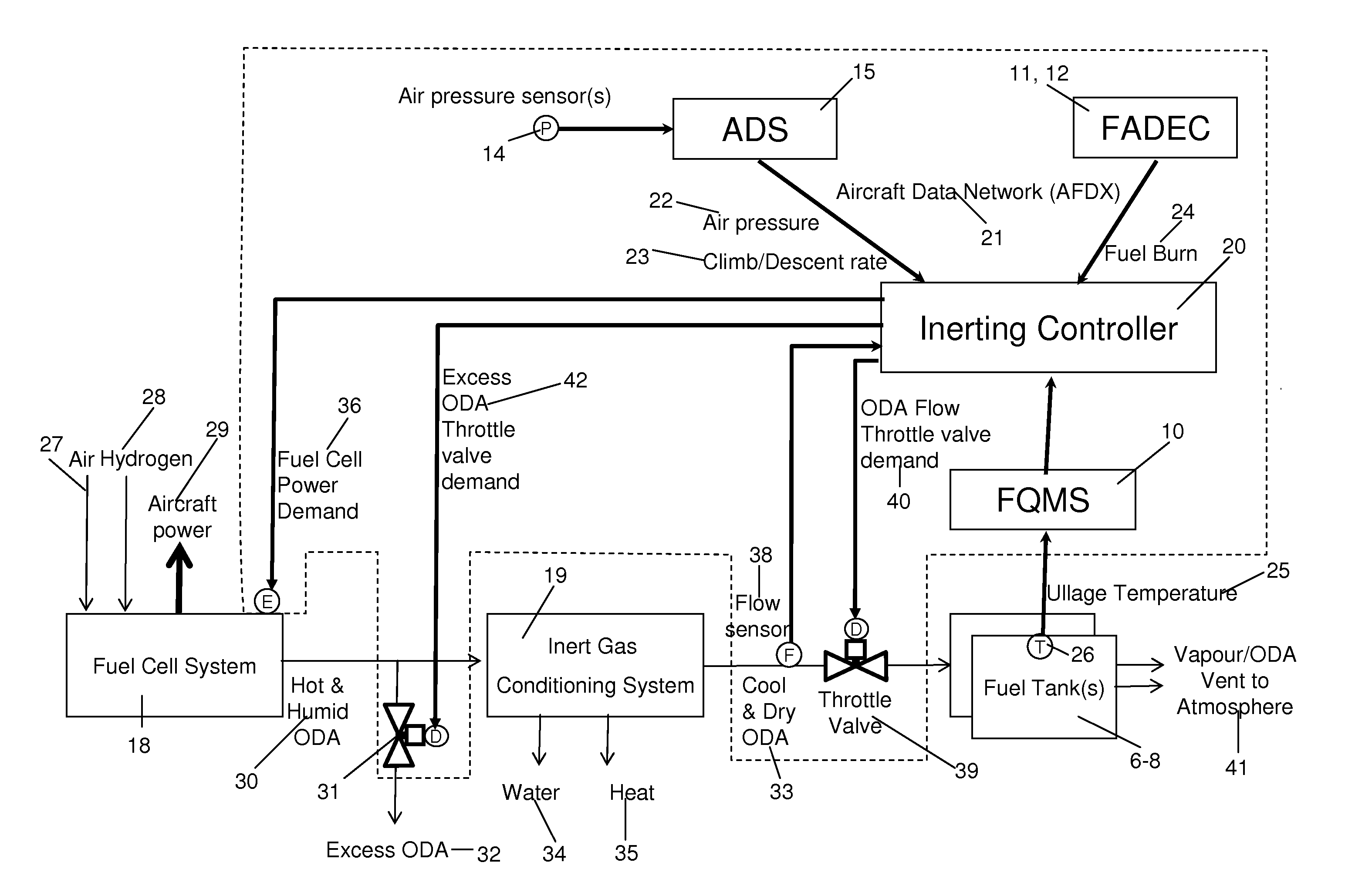
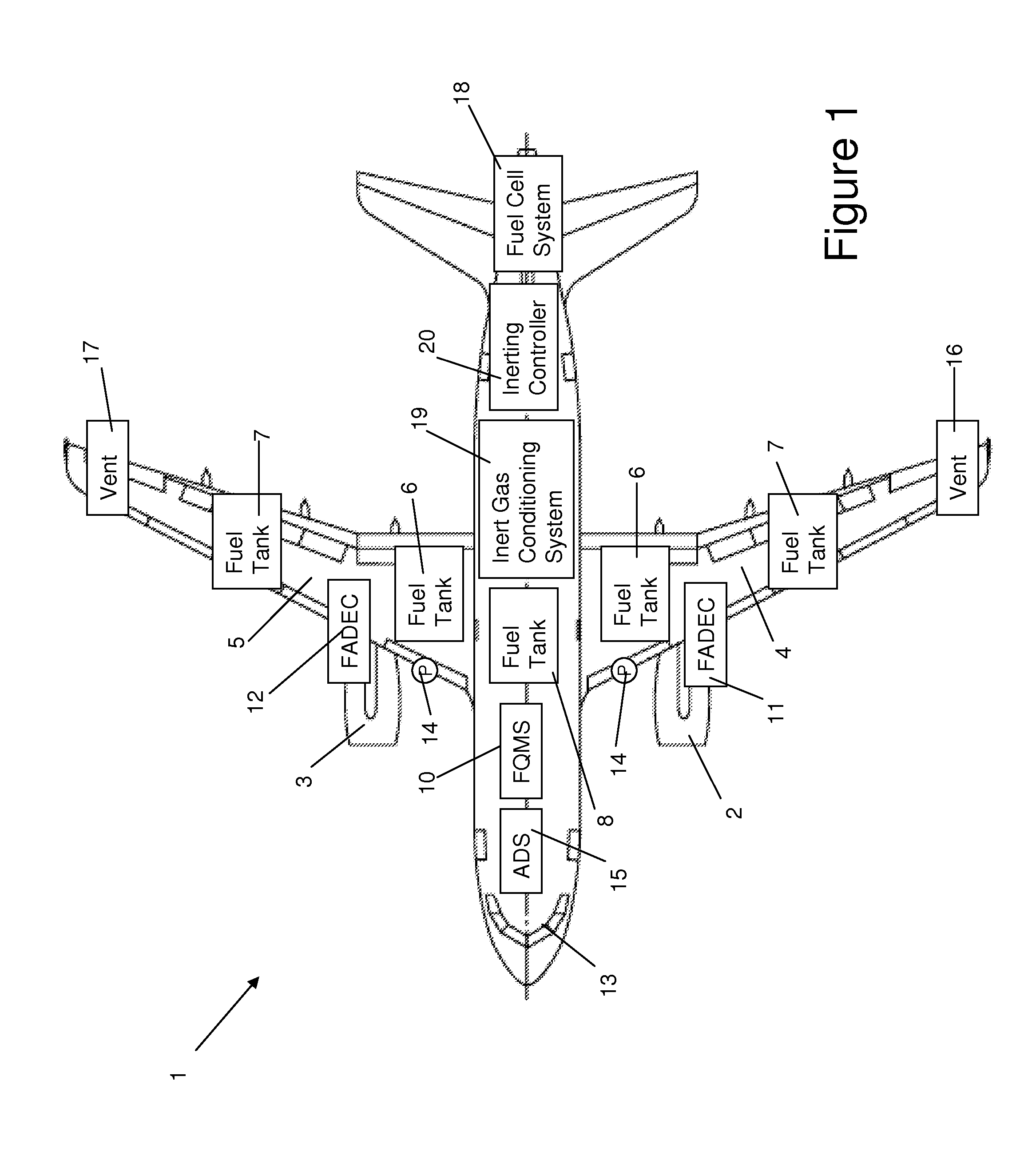
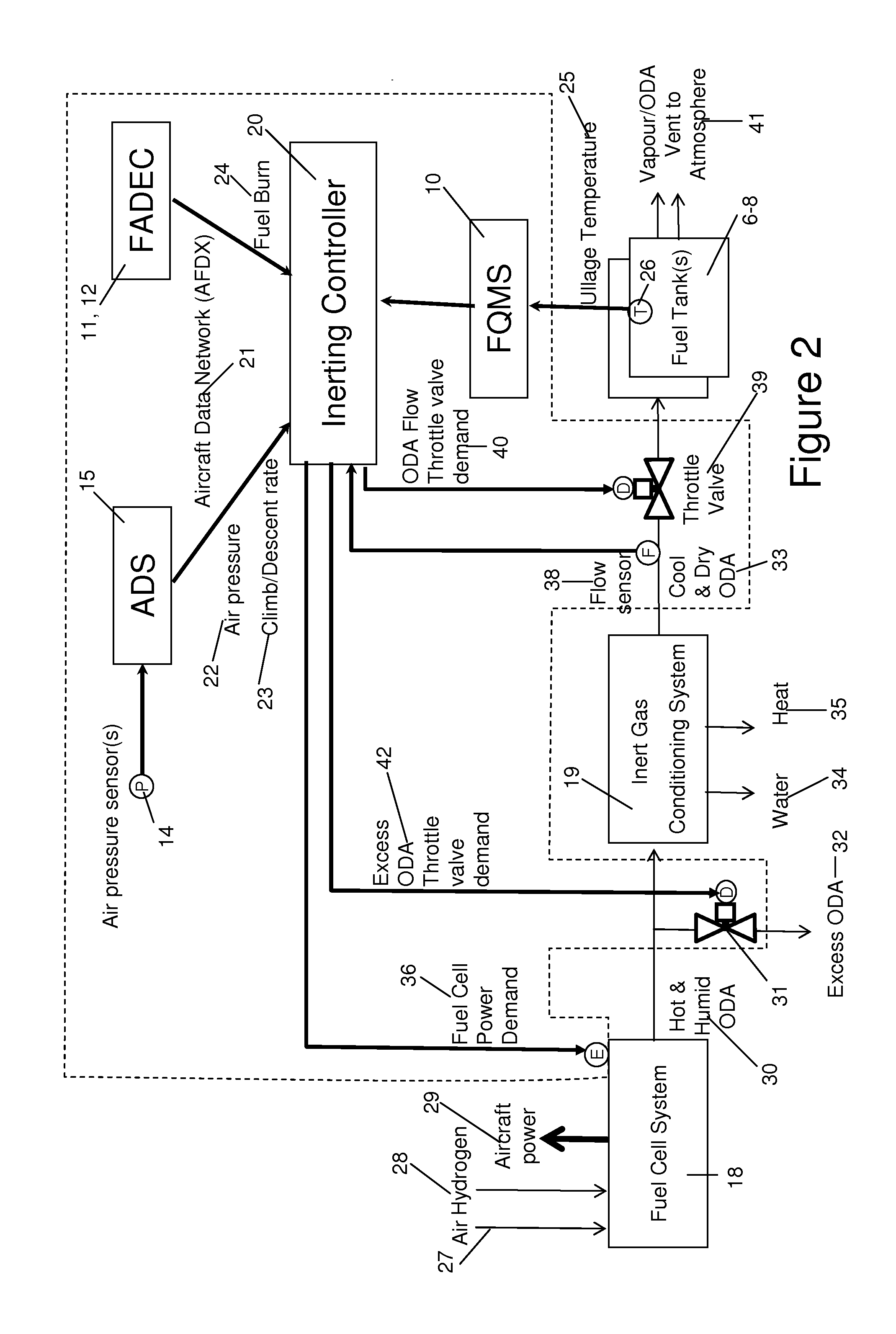
[0039]FIG. 1 illustrates a plan view of an aircraft 1, such as a commercial jet passenger transport aircraft. Various aircraft systems have been schematically superimposed in block form over the plan view of the aircraft for illustration purposes, and their true location should not be inferred from this drawing. The aircraft 1 includes many conventional aircraft systems currently found on existing in-service aircraft, some already proposed systems that will appear on future aircraft, and the controller of this invention which will interface with these systems.

[0040]The aircraft 1 includes main engines 2, 3, which in this example are twin under-wing mounted jet engines. The wings 4, 5 include integral fuel tanks 6, 7 and there is a further centre fuel tank 8 in the centre wing box, in a conventional manner. A fuel quantity monitoring system (FQMS) 10 interfaces with a plurality of sensors for sensing various fuel parameters of fuel within the fuel tanks 6-8. These may include fuel l...


PUM


Abstract

A method of controlling a flow rate of inerting gas introduced into a vented aircraft fuel tank, the method comprising: monitoring changes in a quantity of a fuel in the aircraft fuel tank; monitoring changes in the ambient air pressure external to the aircraft fuel tank; and actively controlling a flow rate of inerting gas, {dot over (m)}(I), introduced into the aircraft fuel tank based upon changes in the quantity of fuel in the fuel tank and changes in the ambient air pressure, p. Also, an aircraft including a vented fuel tank, a supply of inerting gas for rendering inert the fuel tank ullage, and a controller for performing the method.

Description

FIELD OF THE INVENTION[0001]The present invention relates to methods and apparatus for introducing inert gas into a vented aircraft fuel tank.BACKGROUND OF THE INVENTION[0002]Following in-service incidents of aircraft fuel tank explosions, new regulations to achieve flammability reduction in fuel tanks have been introduced for new commercial aircraft.[0003]The relevant FAA Regulation states: “A fuel tank is considered inert when the bulk average oxygen concentration within each compartment of the tank is 12 percent or less from sea level up to 10,000 feet altitude, then linearly increasing from 12 percent at 10,000 feet to 14.5 percent at 40,000 feet altitude, and extrapolated linearly above that altitude.”[0004]Typically this is achieved by continuously adding Nitrogen to the fuel tank ullage during operation and keeping the Ullage Gas Oxygen Fraction (UGOF) below 11%. Currently, one solution is to use Air Separation Modules (ASMs) to molecularly separate the Nitrogen from the Oxyg...

Claims


Application Information

Patent Timeline
IPC IPC(8): B64D37/32B64D37/06
CPCB64D37/32B64D37/06B64D2041/005Y10T137/0379Y10T137/3099Y02T50/40Y02T90/40
Inventor TICHBORNE, FRANKLINHUGHES, BRIANRENOUARD-VALLET, GWENAELLE MARIE LUCETTEBURNELL, STEPHEN EDWARD
Owner AIRBUS OPERATIONS LTD
Why Eureka
Try Eureka