Electronic device, package, electronic apparatus, and moving object

a technology of electronic equipment and moving objects, applied in the direction of devices, devices, instruments, etc., can solve the problems of reducing the reliability of mechanical and electrical connection to the ic for oscillating circuit (an electronic element) by the bonding wire, spoiled terminals (bonding pads), and deteriorating wire bondability of terminals

Inactive Publication Date: 2014-08-28
SEIKO EPSON CORP
View PDF9 Cites 10 Cited by
  • Summary
  • Abstract
  • Description
  • Claims
  • Application Information

AI Technical Summary

Benefits of technology

[0033]According to this application example, the moving object includes the electronic device or the package according to any one of the application examp

Problems solved by technology

As a result, in the piezoelectric oscillator (an electronic device), flatness of the terminals (bonding pads) is spoiled.
Therefore, it is likely that wire bondability of the terminals is deteriorated and reliability of mechanical and electrical connection to the IC for os

Method used


Image

  • Electronic device, package, electronic apparatus, and moving object
  • Electronic device, package, electronic apparatus, and moving object
  • Electronic device, package, electronic apparatus, and moving object

Examples


first embodiment

[0041]First, a physical quantity sensor as an example of an electronic device is explained.

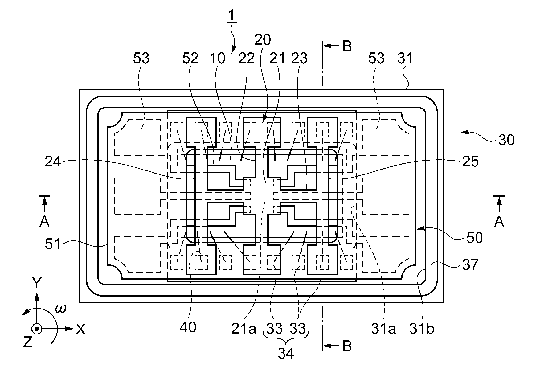
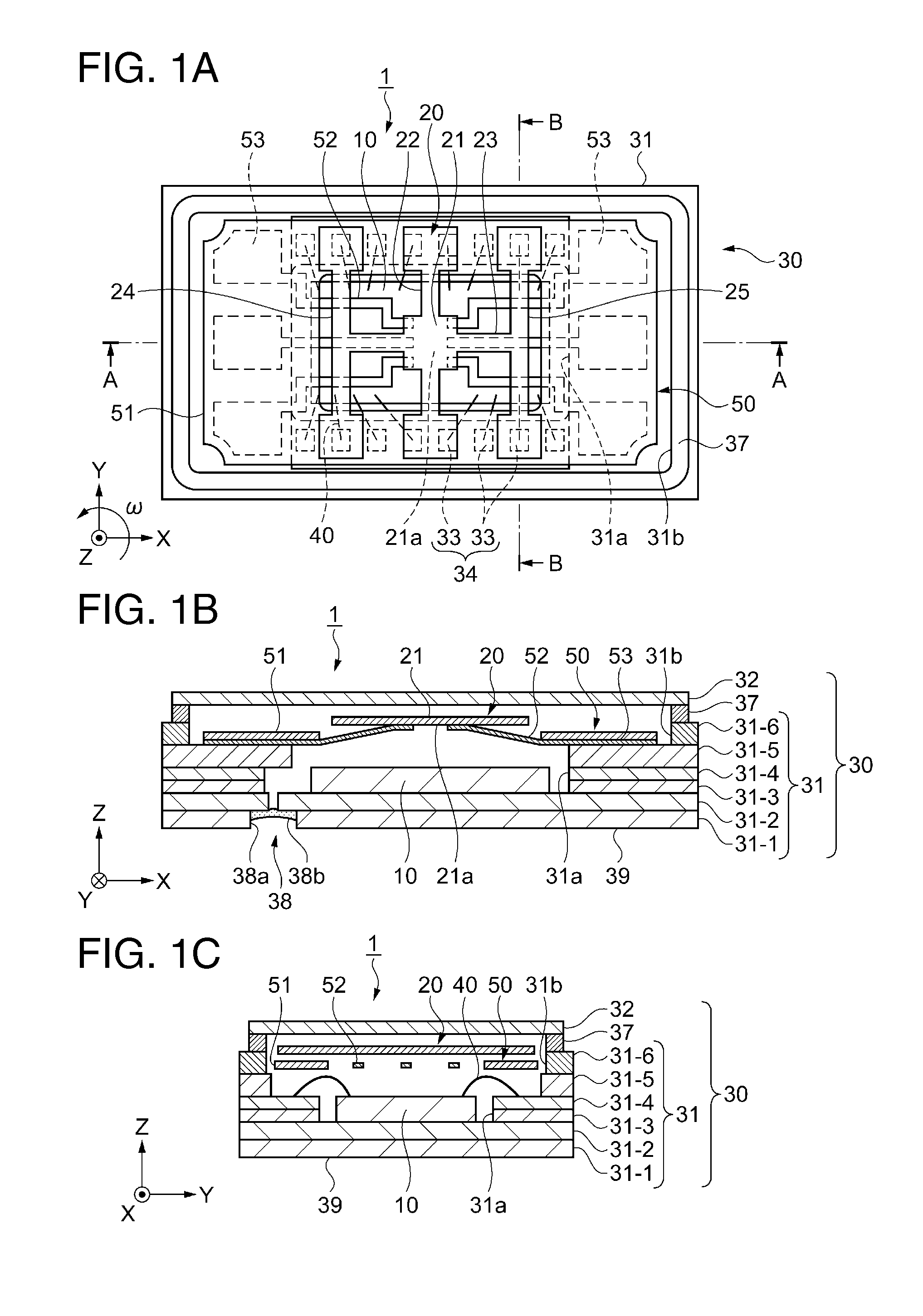
[0042]FIGS. 1A to 1C are schematic plan sectional views showing the schematic configuration of a physical quantity sensor in a first embodiment. FIG. 1A is a schematic plan view of the physical quantity sensor overlooked from a lid side, FIG. 1B is a schematic sectional view taken along line A-A in FIG. 1A, and FIG. 1C is a schematic sectional view taken along line B-B in FIG. 1A.

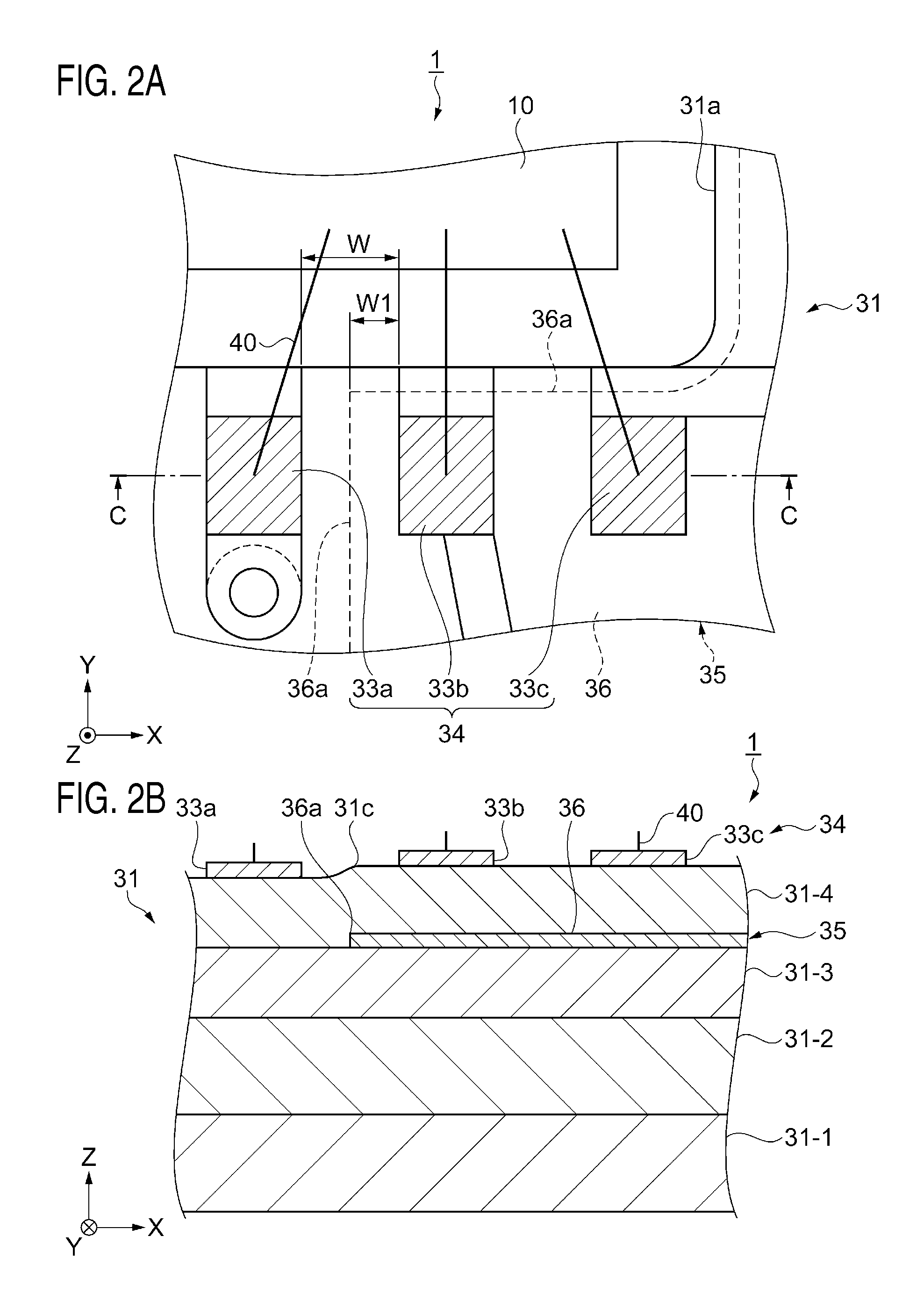
[0043]FIGS. 2A and 2B are main part enlarged schematic diagrams of FIGS. 1A to 1C. FIG. 2A is a schematic plan view and FIG. 2B is a schematic sectional view taken along line C-C in FIG. 2A.

[0044]Note that, in schematic plan views referred to below, for convenience of explanation, a part of components such as a lid are not shown. In schematic diagrams referred to below, to facilitate understanding, dimension ratios of the components are set different from actual dimension ratios. An X axis, a Y axis, and a Z axis in t...

second embodiment

[0106]An electronic apparatus including the electronic device explained above is explained.

[0107]The electronic devices such as the physical quantity sensor 1 (the gyro sensor), the acceleration sensor, the pressure sensor, the weight sensor, and the piezoelectric oscillator can be suitably used as a sensor device including a sensing function and a timing device, which generates a reference clock, in electronic apparatuses such as a digital still camera, a video camera, a pointing device, a game controller, a cellular phone, and a head-mounted display. In all the cases, it is possible to provide the electronic device excellent in reliability that reflects the effects explained in the embodiments.

[0108]An example of the electronic apparatus is explained below.

[0109]FIG. 4 is a perspective view showing a cellular phone as an example of the electronic apparatus in a second embodiment.

[0110]As shown in FIG. 4, a cellular phone 200 includes a plurality of operation buttons 202, an ear pi...

third embodiment

[0112]A moving object including the electronic device explained above is explained.

[0113]FIG. 5 is a schematic perspective view showing an automobile as an example of the moving object in a third embodiment.

[0114]In an automobile 300 shown in FIG. 5, the physical quantity sensor 1 functioning as the electronic device is used as a posture detection sensor of a navigation device or a posture control device mounted on the automobile 300.

[0115]According to the third embodiment, the automobile 300 includes the physical quantity sensor 1. Therefore, the effects explained above in the embodiments are reflected, reliability is improved, and excellent performance can be displayed.

[0116]In the automobile 300, a piezoelectric oscillator functioning as the electronic device can be suitably used as, for example, a timing device configured to generate a reference clock for various electronic control devices (e.g., an electronically controlled fuel injection device, an electronically controlled AB...


PUM


Abstract

A physical quantity sensor includes an IC chip and a package base mounted with the IC chip. The package base includes a first wiring layer provided with bonding pads connected to the IC chip via a bonding wire, a second wiring layer overlapping the first wiring layer in plan view, and an insulating layer provided between the first wiring layer and the second wiring layer. A contour of a wiring pattern provided on the second wiring layer (of the second wiring layer) is arranged in a position not overlapping the bonding pads in plan view.

Description

BACKGROUND[0001]1. Technical Field[0002]The present invention relates to an electronic device and to an electronic apparatus and a moving object including the electronic device.[0003]2. Related Art[0004]As an example of an electronic device, there has been known a piezoelectric oscillator. In the piezoelectric oscillator, a piezoelectric transducer is laminated on the upper surface of a ceramic container including an IC (integrated circuit) for oscillating circuit arranged in a recess formed on the upper surface thereof. A terminal for performing electrical connection to the IC for oscillating circuit by a bonding wire is provided on the bottom surface in the recess of the ceramic container. When the terminal is connected to terminals for transducer connection of the IC for oscillating circuit, the terminals can change the connection without crossing one another (see, for example, JP-A-2006-114976 (Patent Literature 1).[0005]In an embodiment in Patent Literature 1, in the piezoelect...

Claims


Application Information

Patent Timeline
IPC IPC(8): H01L41/02H01L23/48
CPCH01L41/02H01L23/48H01L24/32H01L24/45H01L24/48H01L24/73H01L2224/32225H01L2224/45124H01L2224/45144H01L2224/45147H01L2224/48091H01L2224/48227H01L2224/73265H01L2924/14H01L2924/15151H01L2924/15153G01C19/5628H01L2924/12042H01L2924/16195H01L2924/00012H01L2924/00H01L2924/00014
Inventor AOKI, SHINYA
Owner SEIKO EPSON CORP
Why Eureka
Try Eureka