
Remediation of contaminated particulate materials

a technology of particulate materials and contaminated materials, which is applied in the direction of combustion types, lighting and heating apparatus, incinerator apparatus, etc., can solve the problems that the level of organic contaminant concentration of the fuel with insufficient levels of the fuel may still be considered contaminated according to regulatory standards, and achieves the effects of increasing the fuel content, promoting smoldering, and increasing cost-effectiveness

Active Publication Date: 2014-08-28
EXXON RES & ENG CO
View PDF3 Cites 13 Cited by
  • Summary
  • Abstract
  • Description
  • Claims
  • Application Information

AI Technical Summary

Benefits of technology

The patent text describes a method for remediation of contaminated particulate materials through smoldering. The method uses an additive, such as peat or humalite, to increase the fuel content of the material and promote smoldering. The additive can be introduced in either in situ or ex situ remediation. The addition of the additive can be done using a liquid fuel, such as biodiesel or bioethanol, which can be injected through injection wells and sustain the smoldering front as it progresses through the treatment bed. The method can also involve continuous mass-flow design for more efficient and continuous operation. The technical effects of the patent text include improved remediation of contaminated particulate materials, increased treatment temperatures, mitigation of fluctuations in the particulate material, and improved quality and beneficial reuse of smoldered product.

Problems solved by technology

Particulate materials with insufficient levels of these fuels may nonetheless have high enough organic contaminant concentrations to be considered contaminated according to regulatory standards.

Method used


Image

  • Remediation of contaminated particulate materials
  • Remediation of contaminated particulate materials
  • Remediation of contaminated particulate materials

Examples


example 1

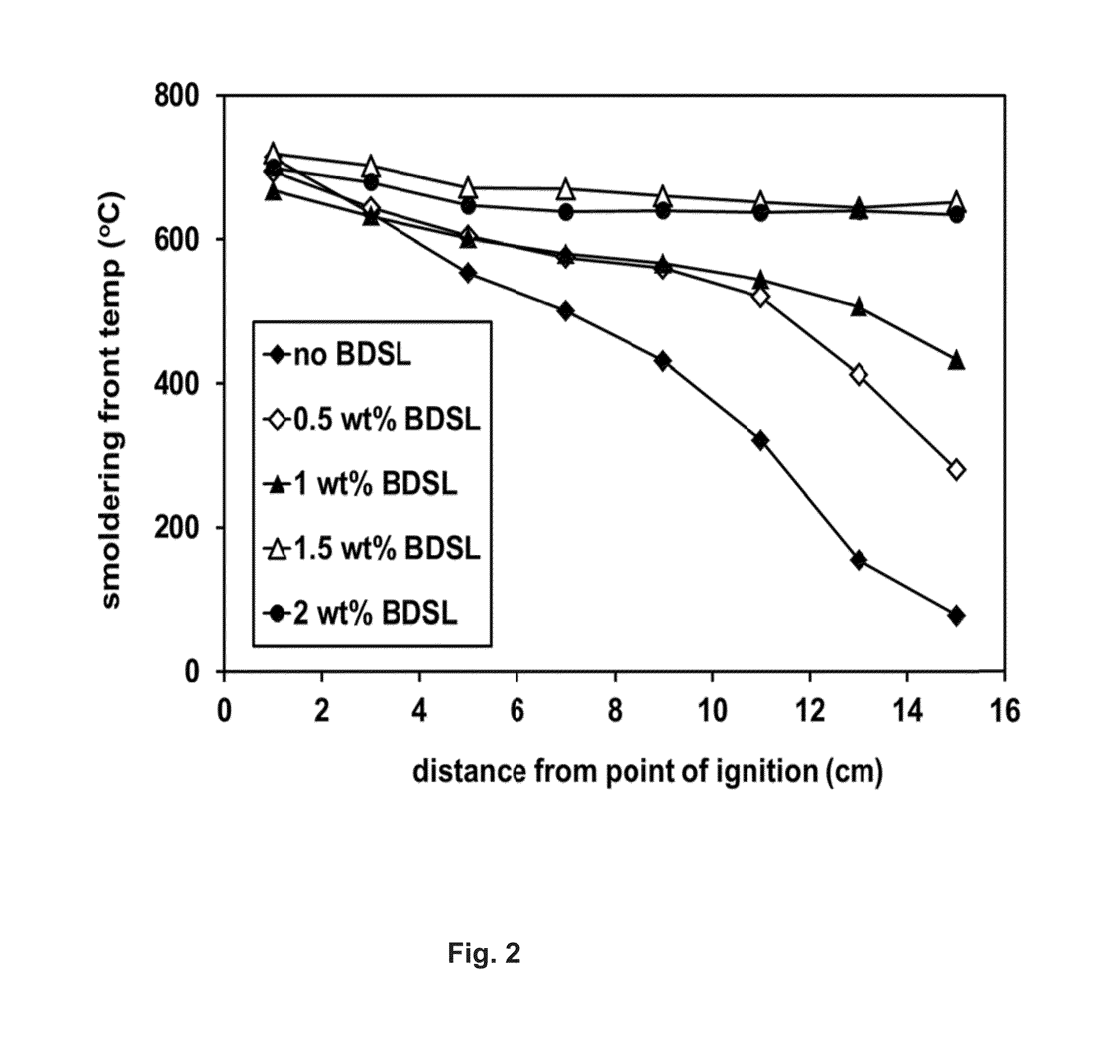
[0042]Biodiesel (“BDSL”) was added to soils at concentrations between 0 and 2 weight percent and the prepared soils were subject to benchtop smoldering tests as described above. The temperature profiles (FIG. 2) show how the addition of biodiesel to the soil causes a transition from an unsustainable process (smoldering front cools as it moves up the soil column) to a self-sustaining one at 1.5 weight percent biodiesel (smoldering front temperatures stabilize above 600° C.). The soil analysis (FIG. 3) demonstrates that adding sufficient biodiesel to the soil to achieve a self-sustaining process allows for effective removal of soil hydrocarbons in the range of C16-C34, which includes the added biodiesel.

example 2

[0043]Humalite (“Hum”), a material rich in humic acids, was mixed into soils at concentrations between 0 and 3 dry weight percent. The prepared soils then underwent benchtop smoldering tests as described above, which demonstrated that the addition of 1.5 dry weight percent humalite was sufficient to establish self-sustaining smoldering (temperatures stabilize near 600° C. as the front moves up the soil column). In addition, increasing the concentration of humalite to 3 dry weight percent increased the stable front temperature to about 700° C., which would enhance contaminant oxidation and reduce harmful emissions. The results are shown graphically in FIG. 4.

example 3

[0044]As demonstrated by fireflooding, a smoldering front not only destroys hydrocarbons, but mobilizes them. A benchtop smoldering experiment with an oil-contaminated soil sample showed that some oil migrates ahead of the smoldering combustion front (into a layer of ceramic beads in the experiment). This migration may complicate an in situ application, as contaminants can accumulate at the periphery of the treatment area. Such contaminant “halos” could even require subsequent ex situ treatment or disposal. In the continuous ex situ system, outward migration of organic contaminants is limited by the walls of the chamber, which can be insulated to maximize combustion, and volatile contaminants can be captured by the air emissions control system. Since non-volatile contaminants cannot effectively escape the hot zone, a larger proportion may be destroyed.


PUM


Abstract

A process for the remediation of contaminated particulate materials by the addition of an environmentally benign, carbonaceous fuel source in low concentration to enable or enhance smoldering combustion. The process may be applied to both in situ and ex situ treatments. In an ex situ smoldering process for the remediation of contaminated particulate materials in a continuous manner, contaminated feed is introduced near the top of a treatment unit and treated product emerges near the bottom. A smoldering front is maintained in the unit, fed by the fuel in the contaminated particulate material and a supply of combustion-supporting gas, such as air.

Description

FIELD OF THE INVENTION[0001]The presently disclosed subject matter relates to the remediation of particulate materials contaminated with organic compounds. In particular, the presently disclosed subject matter relates to a process for the application of smoldering combustion to remediate contaminated particulate materials.BACKGROUND OF THE INVENTION[0002]Contamination of particulate materials (e.g., soils, sediments, sludges, or muds) can arise from hazardous materials being spilled, leaked, discharged, co-processed, or buried at a site, or from intrusion of contaminants from offsite sources. As an example, leaking underground storage tanks have contaminated the soil at sites with petroleum hydrocarbons and lead, and caused similar contamination of adjacent sites through migration in the subsurface. In general, contaminants which may be found in particulate materials include liquids, which may have associated vapors, and solids. Contaminants may be physically or chemically attached ...

Claims


Application Information

Patent Timeline
Patent Type & Authority Applications(United States)
IPC IPC(8): B09C1/06
CPCB09C1/06B09C2101/00F23G7/14F23G2201/701
Inventor ROCKWELL, GREGORY PAULLACHINE, RANDALL STEPHENJAJUEE, BABAK ADAMBARNES, BRADLEY SCOTTMAI, RAINER DETLEF
Owner EXXON RES & ENG CO
Learn More