Reversible Camouflage Material

a camouflage material and reversible technology, applied in the field of camouflage materials, can solve the problems of poor nir camouflage durability of textile materials, wash and/or wear, and coatings can affect the visible, nir, swirl camouflage properties of textiles,

Inactive Publication Date: 2014-08-28
WL GORE & ASSOC INC
View PDF2 Cites 21 Cited by
  • Summary
  • Abstract
  • Description
  • Claims
  • Application Information

AI Technical Summary

Benefits of technology

[0014]It is yet another feature of the present invention that the nIR and SWIR reflectance can

Problems solved by technology

A disadvantage to this technique is that the carbon can negatively impact the desired visible shade of the camouflage textile and frequently results in a compromise between achieving appropriate visible and nIR camouflage, particularly in environments which require extremely light shades like the desert.
In addition, topically treating textiles with such a carbon finish results in a textile material with poor nIR camouflage durability, as the topical carbon finishing can readily wash and/or wear off in use.
A further challenge in creating camouflage textiles which are suitable

Method used


Image

  • Reversible Camouflage Material
  • Reversible Camouflage Material
  • Reversible Camouflage Material

Examples


example 1

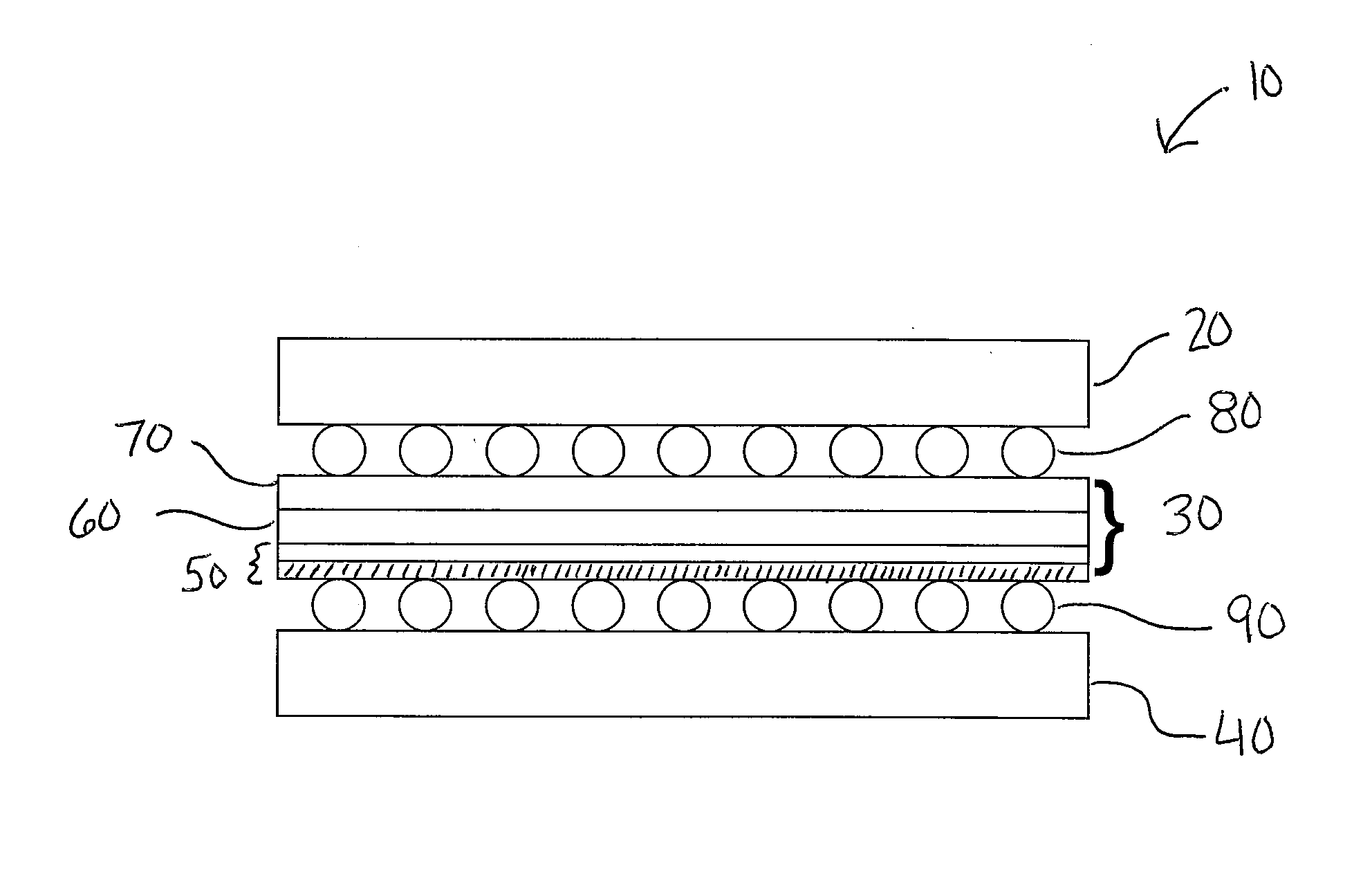
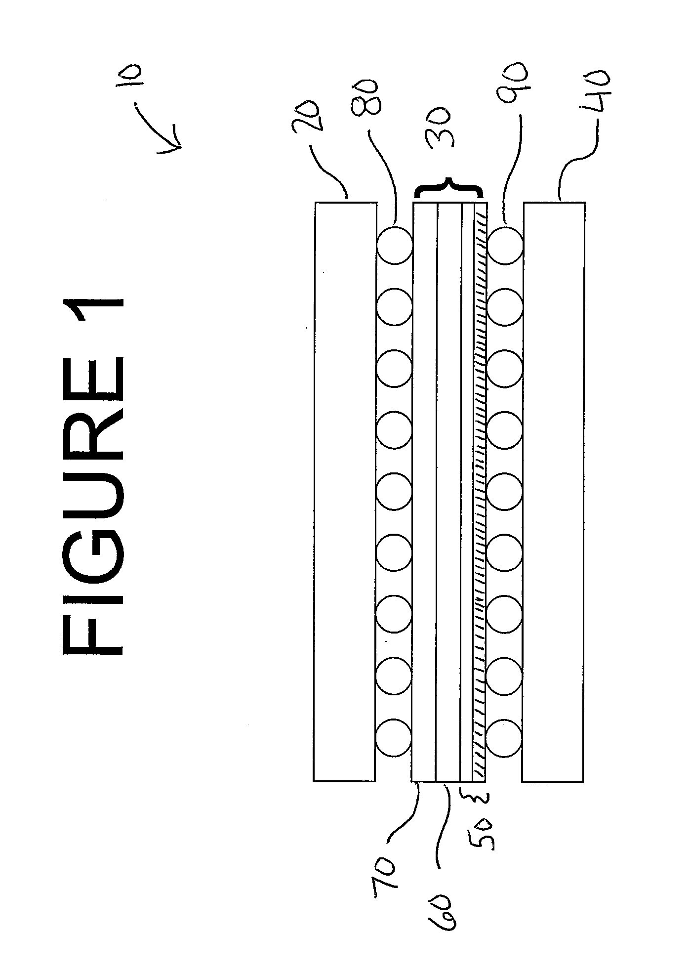
[0052]A reversible garment material was constructed in the following manner. A 30 denier (30D) by 30 denier (30D) printed, woven woodland MARPAT camouflage fabric with carbon incorporated into the ink used in the printing process is bonded as follows:

[0053]1) A three-layer film composite, approximately 0.27 mm thick was obtained consisting of a polyurethane layer sandwiched between two ePTFE layers. This laminate was constructed in accordance with the general teachings of U.S. Pat No. 5,418,054 to Sun except that no phosphorous or other flame-retardant material was incorporated into the polyurethane layer. A fluoroacrylate, carbon-containing coating (to aid in controlling nIR reflectance), as generally taught in U.S. Patent Publication No. 2007 / 0009679 to Holcombe, et al. was then applied to one side of the film laminate in order to render it oleophobic while preserving the microporous structure.

[0054]2) The bond of the woodland MARPAT fabric layer to the 3 layer film composite was ...

example 2

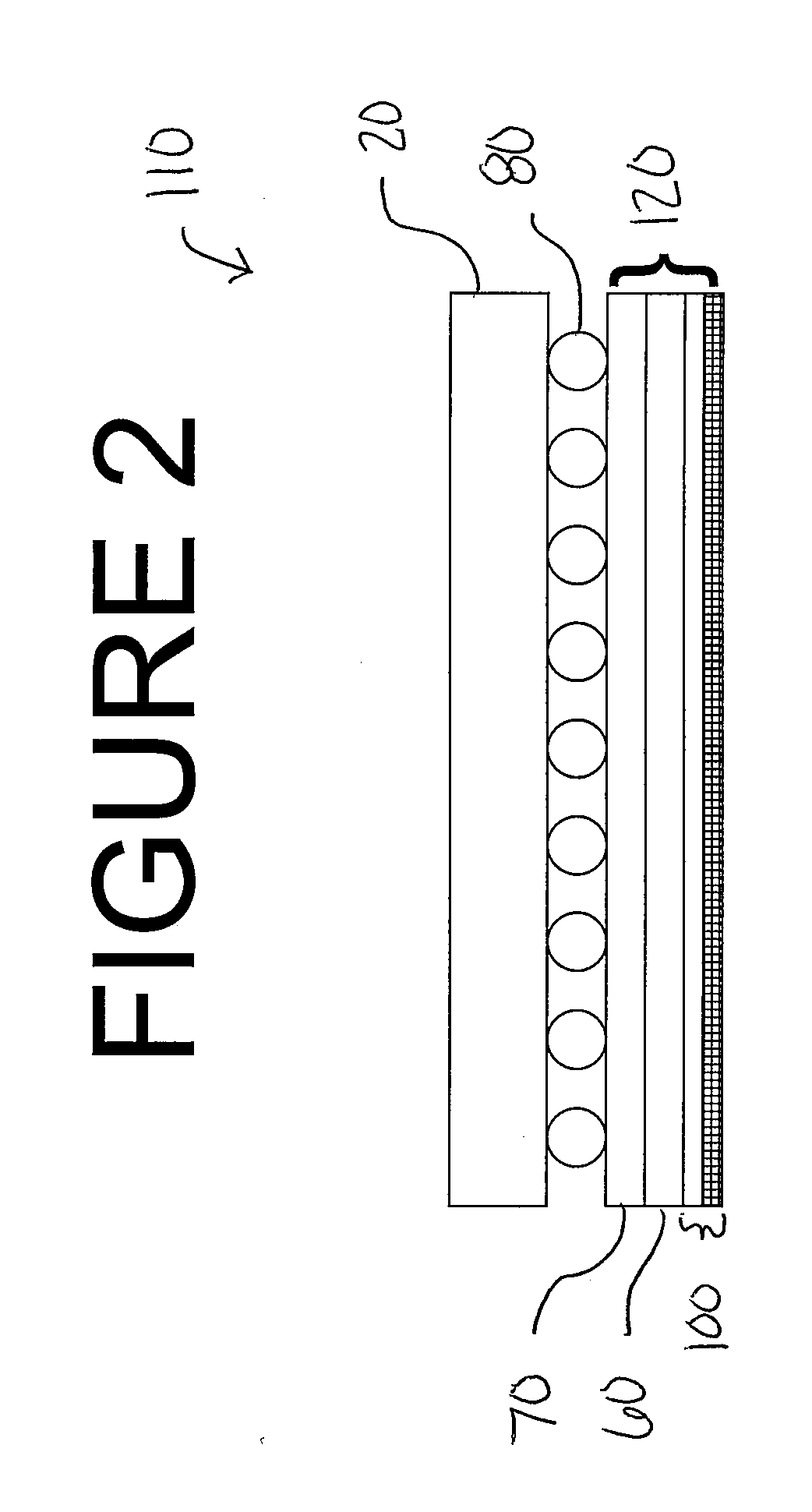
[0059]A reversible garment material was constructed in the following manner. A 30D by 30D printed, woven woodland MARPAT camouflage fabric with carbon incorporated into the ink used in the printing process is bonded as follows:

[0060]1) A three-layer film composite, approximately 0.17 mm thick was obtained consisting of a polyurethane layer sandwiched between two ePTFE layers. This laminate was constructed in accordance with the general teachings of U.S. Pat. No. 5,418,054 to Sun except that no phosphorous or other flame-retardant material was incorporated into the polyurethane layer.

[0061]2) The bond of the woodland MARPAT fabric layer to the 3 layer film composite was made by applying a dot pattern of a melted polyurethane adhesive to the 3 layer film composite. While the polyurethane adhesive dots were molten, the fabric was positioned, non-printed side down, on top of the adhesive side of the three layer film composite. This construct was allowed to cool.

[0062]The construct demon...


PUM

PropertyMeasurementUnit
Fractionaaaaaaaaaa
Fractionaaaaaaaaaa
Fractionaaaaaaaaaa

Abstract

A reversible camouflage material including a textile layer having a woodland camouflage print thereon, an infrared suppressing layer, and a textile layer having a desert camouflage print thereon is provided. The infrared suppressing layer may include a polyurethane layer sandwiched between a carbon-containing ePTFE layer and an ePTFE layer. The carbon may be provided in an oleophobic layer on the ePTFE or within the ePTFE film. In one embodiment, the desert camouflage textile is absent and a coating composition that includes a colorant and infrared suppressive additives is applied to the outer surface of the ePTFE layer. The inventive camouflage material demonstrates camouflage concealment in the near IR (nIR) and short wave infrared (SWIR) wavelengths of the electromagnetic spectrum. In addition, the camouflage material is highly breathable and lightweight. The material is particularly suitable for making reversible camouflage garments such as jackets and pants.

Description

FIELD OF THE INVENTION[0001]The present invention relates generally to camouflage materials, and more specifically, to a reversible camouflage material that demonstrates controlled reflectance in both the nIR and SWIR regions of the electromagnetic radiation spectrum on both sides of the garment while demonstrating high breathability on both sides of the material.BACKGROUND OF THE INVENTION[0002]Camouflage textile materials used by hunters and by the military typically provide camouflage in the visible region of the electromagnetic radiation spectrum (400-700 nm). Due to the vastly diverse environments throughout the world, many different camouflage materials exist, including both visibly camouflaged and non-visibly camouflaged materials. The variety of environments (e.g., ranging from woodland to desert) necessitates the use of a variety of colors and patterns to create these camouflage textile materials. For instance, in a military woodland camouflage, the materials often use four...

Claims


Application Information

Patent Timeline
IPC IPC(8): F41H3/02B32B3/10G02B5/20B32B7/12B32B7/14B32B7/02B32B3/26
CPCF41H3/02B32B3/10B32B3/26B32B7/02B32B7/12B32B7/14G02B5/208B32B27/40B32B5/024B32B5/16B32B27/12B32B27/322B32B2255/02B32B2255/26B32B2264/0257B32B2307/30B32B2307/40B32B2307/724B32B2307/7265B32B2437/00B32B2571/00Y10T428/2481Y10T428/24942Y10T428/24998G02B1/18G02B1/04
Inventor CASTILLE, MATTHEW J.
Owner WL GORE & ASSOC INC
Why Eureka
Try Eureka