Exhaust gas dedusting, denitration and desulfuration method for thermal power plant

A technology for thermal power plants and flue gas, which is applied in combustion methods, separation methods, chemical instruments and methods, etc., can solve the problems of reduced thermal efficiency of boilers, increased primary air and flue gas, and poor heat transfer effects, and can achieve the purpose of catalyst use. The effect of less amount, high denitration efficiency and high flame retardancy

Inactive Publication Date: 2012-03-28
NANJING LONGYUAN ENVIRONMENTAL CO LTD
View PDF5 Cites 21 Cited by
  • Summary
  • Abstract
  • Description
  • Claims
  • Application Information

AI Technical Summary

Problems solved by technology

The SCR reaction temperature is relatively suitable, generally no additional heat source is needed to heat the flue gas, and the operating cost is low; the biggest defect is the heavy metals and SO in the flue gas without dust removal 2 Higher content will have adverse effects on the activity of the catalyst, and it will easily cause ash blockage in the downstream equipment reactor. Secondly, for the high dust content flue gas, the flue gas channel of the catalyst must be enlarged to avoid ash blockage, which will reduce the specific area of ​​the catalyst. In this way, the amount of catalyst is increased, which increases the construction and operation costs of SCR. At the same time, the increase in the amount of catalyst also requires a larger reactor, so that the consumption of steel structures also increases; (2) The low dust content layout scheme is as follows Procedure: high-temperature flue gas → air preheater (cooling) → bag filter (dust removal) → FGD (desulfurization) → heater (heating) → SCR reactor (denitration) → chimney (emission); the advantage of this scheme is to enter The dust content of the flue gas of the SCR reactor is reduced, and a smaller catalyst flue gas channel can be selected to greatly increase the specific area of ​​the catalyst, thereby reducing the overall consumption of the catalyst, reducing the initial investment and the operating cost of the catalyst replacement; the biggest defect is that after The flue gas temperature after the desulfurization tower is lower than the reaction temperature required for SCR denitrification, so the flue gas needs to be reheated by a heater. Generally, the reheating system needs to increase energy consumption by about 3%; After the heater, the high-temperature and high-concentration dust will increase the probability of dust blocking and dust accumulation in the air preheater, and the wear of the inner wall will increase, and the dust blocking will lead to poor heat transfer effect, increased exhaust gas temperature, and increased exhaust heat loss. The thermal efficiency of the boiler decreases, increasing the differential pressure between primary air and flue gas, secondary air and flue gas, and increasing the loss of air leakage. In order to meet the air volume required for boiler combustion, the air supply volume of the fan must be increased. Therefore, this solution has a large energy loss , unable to take into account the goal of energy saving
In addition, in the traditional bag filter, the continuous temperature resistance of the filter bag generally does not exceed 250°C, and the filter cloth is generally made of P84, PPS, polytetrafluoroethylene (PTFE) fibers or composited with each other, so it cannot adapt to the high temperature of about 400°C smoke environment

Method used


Image

  • Exhaust gas dedusting, denitration and desulfuration method for thermal power plant
  • Exhaust gas dedusting, denitration and desulfuration method for thermal power plant
  • Exhaust gas dedusting, denitration and desulfuration method for thermal power plant

Examples


Embodiment Construction

[0013] Embodiments of the method of the present invention will be described below in conjunction with the accompanying drawings.

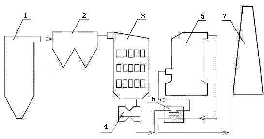
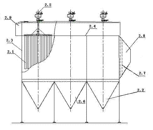
[0014] Such as figure 1 , the high-temperature flue gas (temperature is 380°C~400°C) discharged from the boiler 1 of the thermal power plant is filtered and dusted by the bag filter 2 and then enters the SCR reactor 3 for catalytic reaction, so that the NO in the flue gas X reduced to N 2 Then the high-temperature flue gas enters the air preheater 4 to exchange heat with the air, and the temperature of the flue gas at the outlet of the air preheater 3 reaches 150-160°C, and then passes through the heat exchanger 6 to exchange heat with the low-temperature flue gas after desulfurization, and the flue gas The gas temperature drops to 90-100°C, enters the desulfurization tower 5, and sprays the rising flue gas in the tower with limestone slurry to absorb the SO 2 , the generated gypsum slurry settles to the bottom of the tower, after desulfuriza...


PUM


Abstract

The invention relates to an exhaust gas dedusting, denitration and desulfuration method for a thermal power plant. According to the invention, after being dedusted firstly by a bag-type dust collector, high-temperature raw exhaust gas is introduced in an SCR (selective catalytic reduction) reactor for performing SCR for realizing denitration, and then, the exhaust gas subjected to denitration passes through an air preheater and a heat exchanger in sequence to be cooled to 90-100 DEG C, and then is subjected to wet desulfuration in a desulfurizer; and the exhaust gas subjected to desulfuration and discharged from the desulfurizer is heated to 100-105 DEG C by the heat exchanger and then enters a chimney to be discharged. In the bag-type dust collector, filter cloth in a filter bag has base cloth which is PBO (Poly-p-phenylenebenzobisthiazole) fiber woven cloth and has two surface layers referring to composite fibrofelts formed by cross-laying of PBO fiber nets and basalt fiber nets, the base cloth is sandwiched between the two surface layers and sewed up into a whole body, the whole body is subjected to hot rolling, singeing and heat shaping, Teflon dipping and drying to finally form high-temperature resistant filter cloth. By the adoption of the high-temperature resistant filter bag, the raw exhaust gas can be dedusted firstly at a high temperature and then is subjected to denitration, therefore, ash fouling of subsequent equipment and damages to a catalyst can be reduced, and the effects of low catalyst consumption and high denitration efficiency can be achieved; and since the catalytic reaction does not need additional heat, the effects of energy saving and emission reduction are achieved.

Description

technical field [0001] The invention relates to a dust removal, denitrification and desulfurization method for flue gas in a thermal power plant, in particular to a denitrification and desulfurization method for bag dust removal under high temperature (above 380°C) conditions. Background technique [0002] In recent years, with the increasingly stringent environmental protection regulations and the gradual rise in fuel prices, energy conservation and environmental protection have been widely valued, and higher requirements have been put forward for the discharge of high-temperature flue gas in thermal power plants and energy conservation and consumption reduction in flue gas treatment, especially It is the emission of NOx in the flue gas that has attracted great attention from the society. In addition to the traditional dust removal and desulfurization treatment, the flue gas also needs to be denitrified to ensure that the SO 2 and NO X Emission standards can be met. At pr...

Claims


Application Information

Patent Timeline
Patent Type & Authority Applications(China)
IPC IPC(8): F23J15/02F23J15/06F23L15/00B01D46/02B01D39/14
CPCY02E20/34
Inventor 李仁刚雷达黄向阳刘轶夏新伟丁炜
Owner NANJING LONGYUAN ENVIRONMENTAL CO LTD
Why Eureka
Try Eureka