Hybrid electric vehicle

a hybrid electric vehicle and electric vehicle technology, applied in the direction of electric generator control, process and machine control, automatic control system, etc., can solve the problems of not being able to directly “jump start” and the generators without switching resistance are not self-exciting, and the effect of reducing the number of electric generators is not good,

Active Publication Date: 2014-08-28
FAIRFIELD MFG CO INC
View PDF11 Cites 99 Cited by
  • Summary
  • Abstract
  • Description
  • Claims
  • Application Information

AI Technical Summary

Benefits of technology

[0005]Switched reluctance (SR) technology is preferably used for the AC traction motors because of their wide constant power range, benign failure modes, low cost, robustness, and design flexibility. For the same reasons, it is desirable to preferably employ switched reluctance (SR) technology for the generator / motor which supplies primary power to the machine. However, unlike IPM generators, SR (switched reluctance) generators are not self-exciting. This is desirable as a fault tolerance feature but must be addressed for the system to function properly. Some initial amount of electrical power must be supplied to initiate power generation in the switched reluctance generator or the system will not operate / generate. If a system contains a high-voltage battery pack it could be used to provide the excitation energy necessary for the switched reluctance generator. However, in the case of ultracapacitors there are conditions where sufficient energy will not be available, for example, at initial installation, and after service or after periods of long shutdown.
[0006]Regardless of the generator technology used, it would be desirable to make use of the generator to start the internal combustion engine. This simplifies the system by eliminating the starter and related solenoids and wiring. It also makes start-stop operation practical since the typical DC brush-type starter motor, solenoid and ring gear are not designed for the large number of cycles needed for start-stop operation. The switched reluctance generator / motor is a large machine relative to a conventional starter and can provide higher cranking torques and speeds. Full-time coupling is also desirable since there is no need to manage pinion-ring gear engagement.
[0008]The solution (for SR excitation and for cranking) is to provide a moderately low power (e.g. 5 kW) DC-DC converter to transfer energy from the vehicle 12 or 24-volt batteries to the ultracapacitor bank. If the 12 or 24-volt batteries are discharged, “jump starting” can be applied at the 12 or 24-volt system. Another advantage of this approach is that relatively low levels of power over a longer period of time can be used to handle the energy transfer. So in cases where a weak battery cannot provide sufficient power to crank the engine, it can provide enough power to charge the ultracapacitor bank to a level that will easily crank the engine. This approach also provides the mechanism for pre-charging both the ultracapacitor bank and the power inverter DC-link capacitor banks without need for the typical arrangement of contactors and current limiting pre-charge resistors.
[0010]For a conventional vehicle, the 24-volt battery is kept charged by an alternator. Alternators are relatively inexpensive but are inefficient and have poor reliability. The need for an alternator can be eliminated by making the DC-DC converter bi-directional so that energy is transferred from the DC Link to the 24-volt system to maintain its state of charge. This helps justify the use of the DC-DC converter which will spend the majority of its life charging the 24-volt system and only upon rare occasions transferring energy to charge the ultracapacitor bank.
[0025]The hybrid controller will control the generator inverter to provide current to the DC-Link bus such that: 1) The DC-link voltage stays above the minimum inverter operating voltage; 2) The ultracapacitor bank voltage is kept as high as possible (short of the 900V limit with a safety margin) provided it retains sufficient storage capability to recapture any kinetic or potential energy currently stored in the vehicle. That is because a higher DC-link voltage results in lower system currents, and thus lower losses; hence better system efficiency; 3) The ultracapacitor bank is fully charged prior to engine shutdown so that, even if the ultracapacitors discharge over time, they will likely retain sufficient energy to restart the engine.

Problems solved by technology

However, unlike IPM generators, SR (switched reluctance) generators are not self-exciting.
However, in the case of ultracapacitors there are conditions where sufficient energy will not be available, for example, at initial installation, and after service or after periods of long shutdown.
However, there are times, for example upon initial installation, when the ultracapacitor bank may be discharged.
It is not practical to directly “jump start” the ultracapacitor bank since very high voltage is necessary (>500 Volts).

Method used


Image

  • Hybrid electric vehicle
  • Hybrid electric vehicle
  • Hybrid electric vehicle

Examples


Embodiment Construction

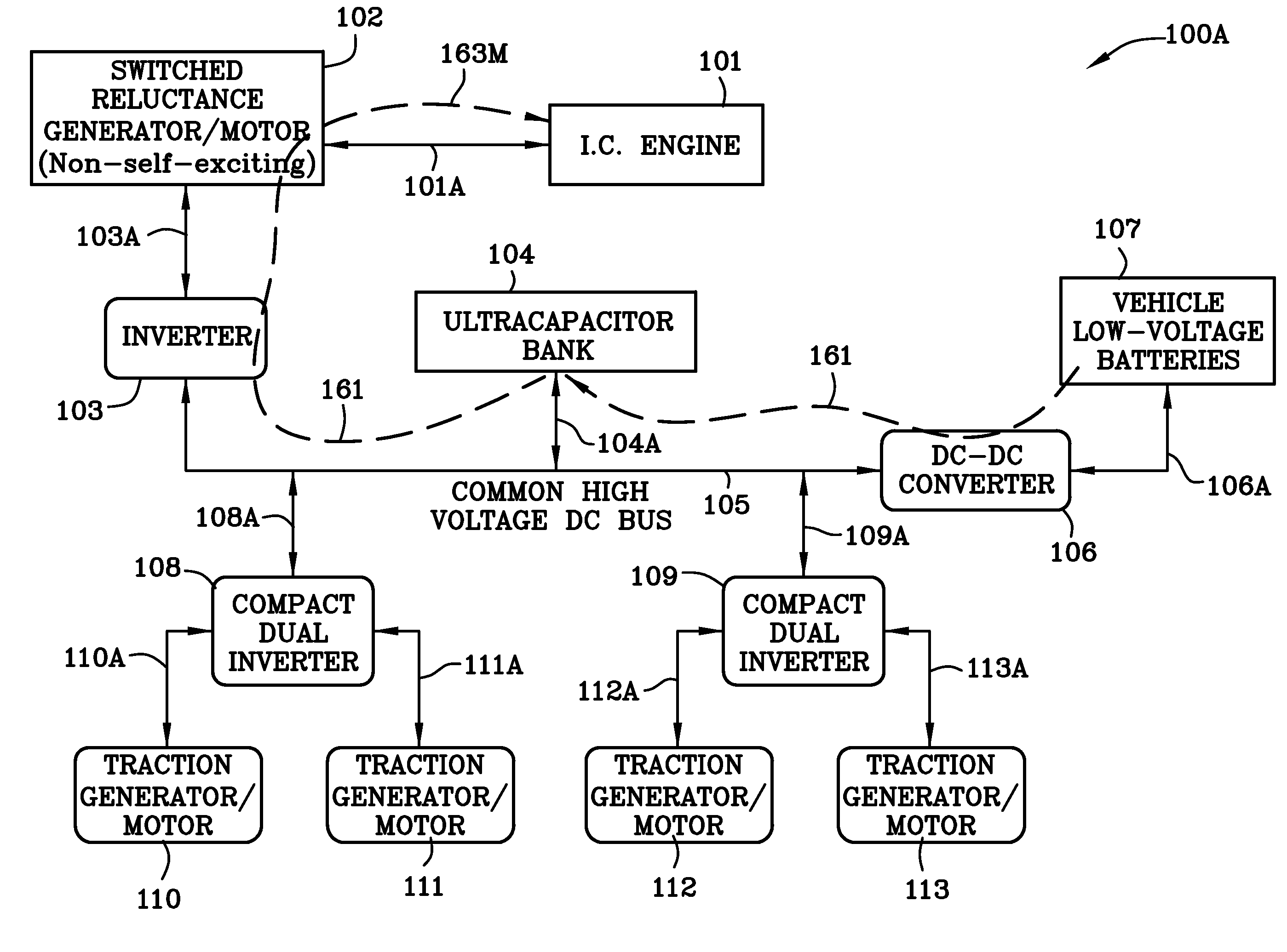
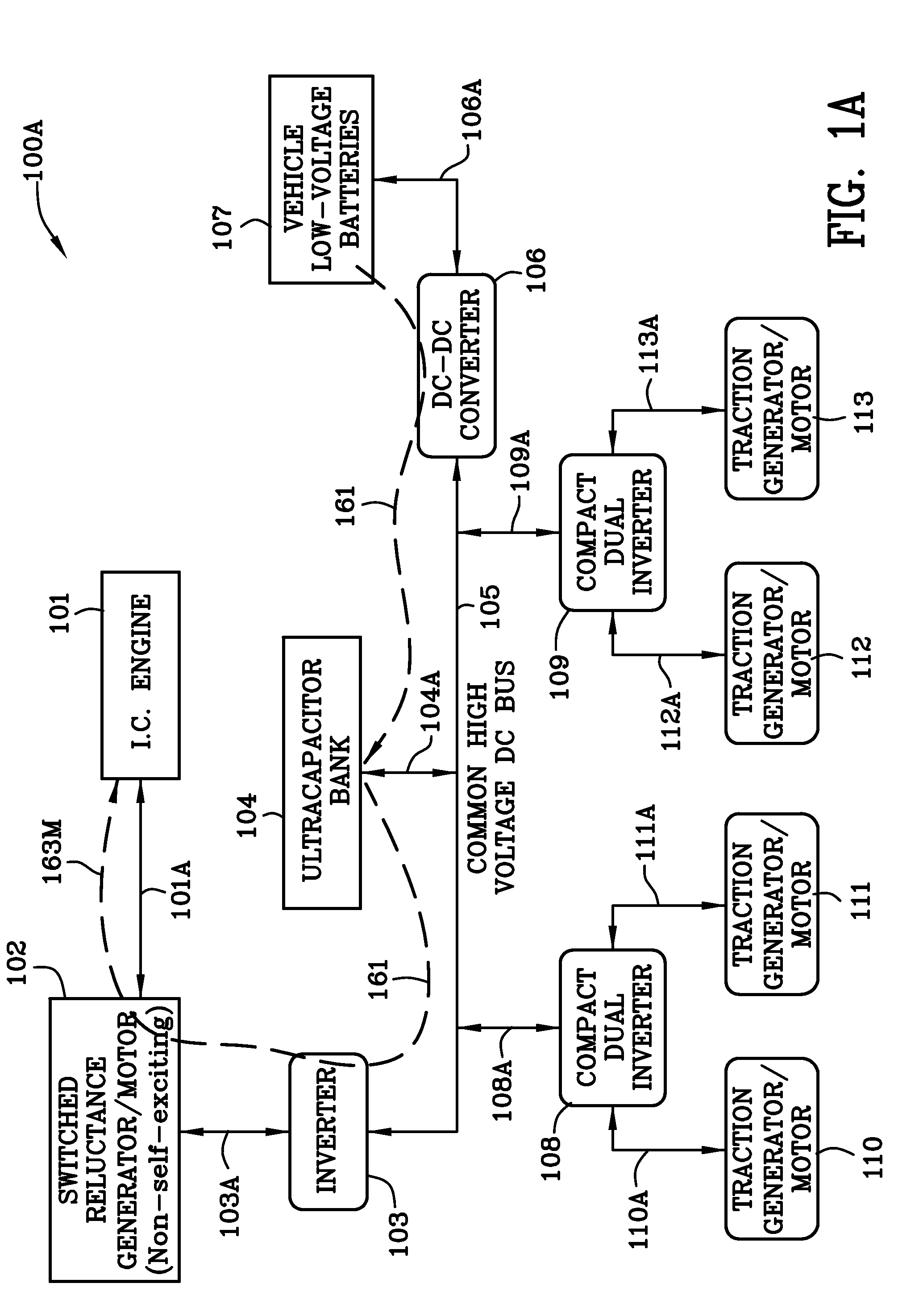
[0068]FIG. 1A is schematic illustration 100A of a hybrid electric vehicle illustrating, inter alia, the condition wherein the ultracapacitor bank 104 is charged from the 24-volt batteries 107 after a prolonged shut-down of the hybrid electric vehicle. FIGS. 1A-1H, inclusive, use many of the same reference numerals and they have the same meaning. Once an element is described in connection with a given reference numeral it will generally not be described again in connection with a subsequent drawing figure to avoid repetition. Reference numeral 161 indicates a dashed line illustrating energy flow along path 161 from the low voltage batteries 107 through the DC-DC converter 106 to the ultracapacitor bank 104, the bidirectional power inverter 103, and the non self-excited switched reluctance generator / motor operating in the motor mode and to the internal combustion engine 101. DC-DC converter 106 is capable of handling 5 kW of power. If the ultracapacitor bank is charged to a sufficient...


PUM


Abstract

A hybrid electric vehicle includes a high voltage DC bus and an internal combustion engine. The internal combustion engine is mechanically coupled to a non self-excited generator / motor which is preferably a switched reluctance machine. A power inverter electrically and bidirectionally couples the high voltage DC bus to the non self-excited switched reluctance generator / motor. Front and rear axle dual DC-AC inverters electrically and bidirectionally couple two traction AC non self-excited switched reluctance motors / gear reducers to the high voltage DC bus for moving the vehicle and for regenerating power. An ultracapacitor coupled to the high voltage DC bus. A bidirectional DC-DC converter interposed between a low voltage battery and the high voltage DC bus transfers energy to the high voltage DC bus and ultracapacitor to ensure that the non self-excited switched reluctance generator / motor operating in the motor mode is able to start the engine.

Description

[0001]This application claims the benefit of and priority to provisional patent application Ser. No. 61 / 769,092 filed Feb. 25, 2013.FIELD OF THE INVENTION[0002]The invention is in the field of hybrid electric vehicles.BACKGROUND OF THE INVENTION[0003]Hybrid electric vehicle technology improves the efficiency of all types of vehicles. Wheel loaders, front end loaders, excavators, combines, sprayers and utility vehicles of all types require improved environmental and financial efficiency.SUMMARY OF THE INVENTION[0004]The wheel loader is a series electric hybrid employing four AC non self-excited switched reluctance traction motors / generators which propel the vehicle and which regenerate power from the kinetic and potential energy of the wheel loader. Alternatively, just one traction motor / generator can be used and it does not necessarily have to be a switched reluctance traction motor / generator. Further, the wheel loader includes a non self-excited switched reluctance generator / motor ...

Claims


Application Information

Patent Timeline
Patent Type & Authority Applications(United States)
IPC IPC(8): B60K6/46H02P9/00B60W10/08B60W20/00B60W10/06B60L50/13B60L50/15
CPCB60K6/46B60W10/06B60W10/08B60W20/108B60W2600/00H02P9/00Y10S903/93B60W20/15H02P25/08B60L50/40B60L50/13B60L50/61H02J1/082B60W2556/00Y02T10/62Y02T10/64Y02T10/70Y02T10/72B60L50/00B60K6/42B60W10/04B60W10/24B60W20/00Y02T10/7072B60K6/22B60K23/08B60W10/00B60Y2200/40B60Y2200/92
Inventor CARON, LAVERNE ANDREW
Owner FAIRFIELD MFG CO INC
Why Eureka
Try Eureka