
Method and apparatus for power storage

a technology of power storage and power supply, applied in the direction of lighting and heating equipment, machines/engines, containers discharging methods, etc., can solve the problems of reducing the efficiency of the supply side in this way, affecting the efficiency the availability of parts of the generation fleet, so as to reduce the energy consumption of the liquefied. , the effect of effective us

Active Publication Date: 2014-09-04
HIGHVIEW ENTERPRISES LTD
View PDF7 Cites 17 Cited by
  • Summary
  • Abstract
  • Description
  • Claims
  • Application Information

AI Technical Summary

Benefits of technology

The patent describes a system for efficiently using cold thermal energy from a cryogenic energy storage system to reduce energy consumption in a liquefaction process. The system includes an expansion turbine that operates at different temperatures to recover and utilize the cold thermal energy. The system also includes a thermal store that operates at very low pressures to minimize costs. The technical effects of the patent include reducing energy consumption, lowering costs, and providing an efficient energy storage device.

Problems solved by technology

As most existing thermal and nuclear power stations are most efficient when run continuously at full load, there is an efficiency penalty in balancing the supply side in this way.
The expected introduction of significant intermittent renewable generation capacity, such as wind turbines and solar collectors, to the networks will further complicate the balancing of the grids, by creating uncertainty in the availability of parts of the generation fleet.
Power storage devices generate power (discharge) on a highly intermittent basis when there is a shortage of generating capacity on the transmission and distribution network.
Such contracts can cover months or even years but typically the time the power provider will be operating (generating power) is very short.
The requirement for two large reservoirs at different elevations, and associated high civil engineering content, can cause installed costs to be very high and limits the number of suitable sites available, many of which have already been exploited.
They are not geographically constrained in the way that pumped hydro and CAES are, however they are relatively high cost, and their efficiency declines with time, limiting their useful lifetime.
The practical difficulties of manufacturing a low cost pressure containment vessel capable of withstanding pressures of at least 100 bar or more typically 150 bar are in the inventors' opinion prohibitive.
For this reason, the inventors believe this approach is not viable.
Firstly, the design will be complex, requiring many high pressure welded joints to be fabricated, yielding an expensive component.
Secondly, the thermal resistance between the high pressure tubes and storage media could result in temperature gradients normal to the flow path and poor thermal performance.

Method used


Image

  • Method and apparatus for power storage
  • Method and apparatus for power storage
  • Method and apparatus for power storage

Examples


Embodiment Construction

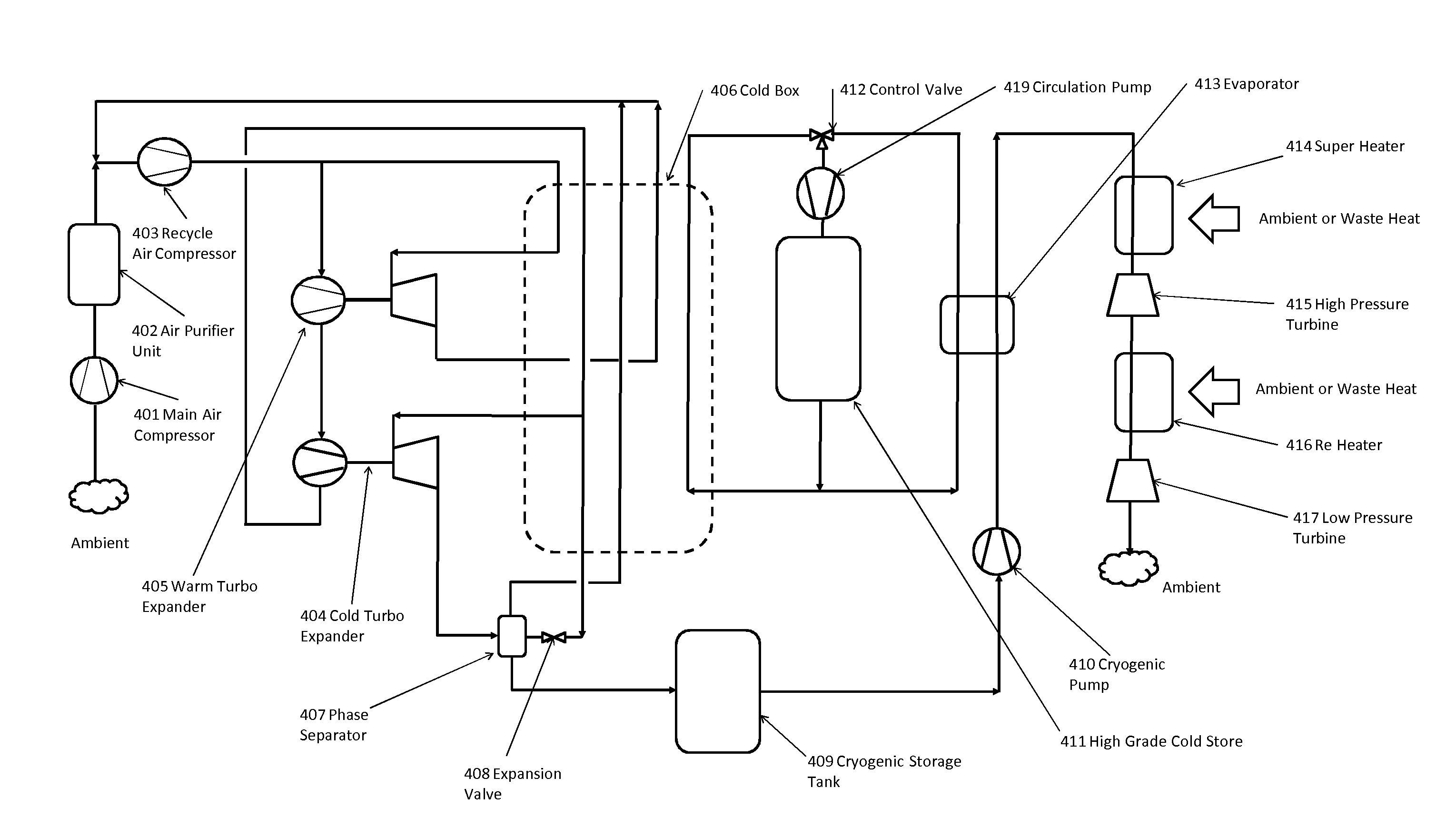
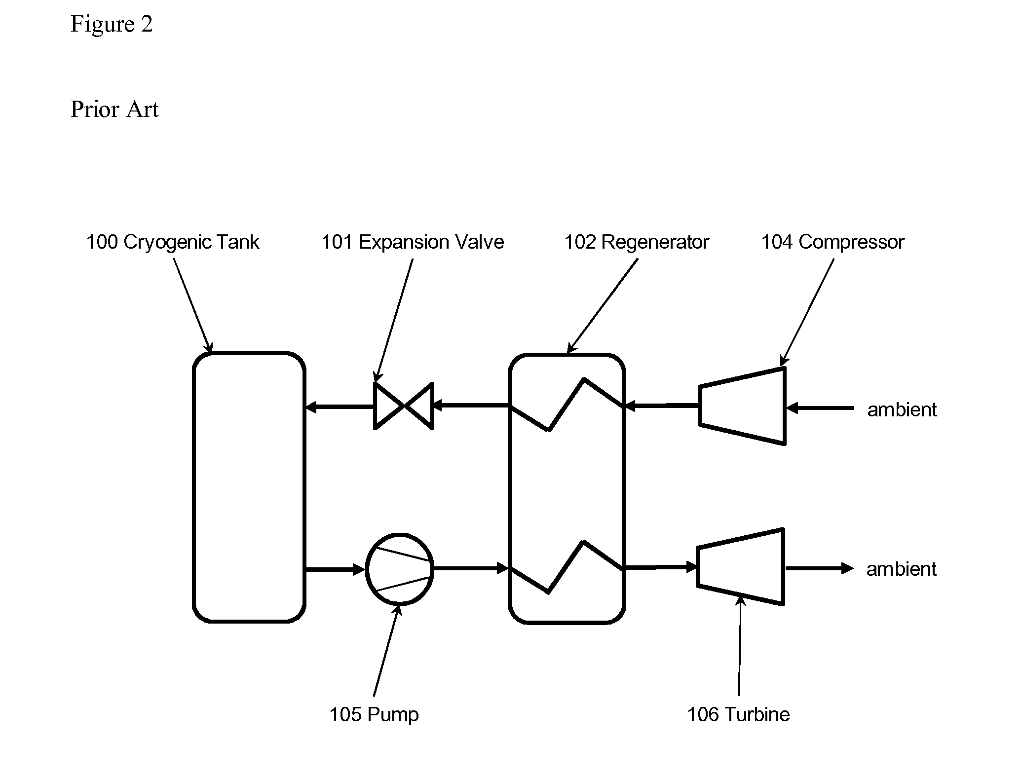
[0156]FIG. 4 shows a schematic of a first simplified embodiment of the present invention. The system of FIG. 4 is similar to that shown in FIG. 2 except that the regenerator shown in FIG. 2, in which the process gasses flow directly through the regenerator, is replaced in FIG. 4 by a thermal store with an intermediate very low pressure heat transfer loop.

[0157]During the power recovery (discharge) phase of the cycle, the cryogenic fluid is first transferred from the storage tank 100 to the pump 105 where the fluid is compressed to high pressure, of at least 30 bar, more preferably at least 50 bar, and more typically 100 to 200 bar. Cold thermal energy is transferred via a heat exchanger, referred to as the evaporator 302, to a heat transfer fluid that circulates between the evaporator and thermal store 301 via a very low pressure heat transfer loop 104. The heat transfer loop typically consists of connecting pipework, a circulation pump and associated instruments and control valves....


PUM


Abstract

Cryogenic energy storage systems, and particularly methods for capturing cold energy and re-using that captured cold energy, are disclosed. The systems allow cold thermal energy from the power recovery process of a cryogenic energy storage system to be captured effectively, to be stored, and to be effectively utilised. The captured cold energy could be reused in any co-located process, for example to enhance the efficiency of production of the cryogen, to enhance the efficiency of production of liquid natural gas, and / or to provide refrigeration. The systems are such that the cold energy can be stored at very low pressures, cold energy can be recovered from various components of the system, and / or cold energy can be stored in more than one thermal store.

Description

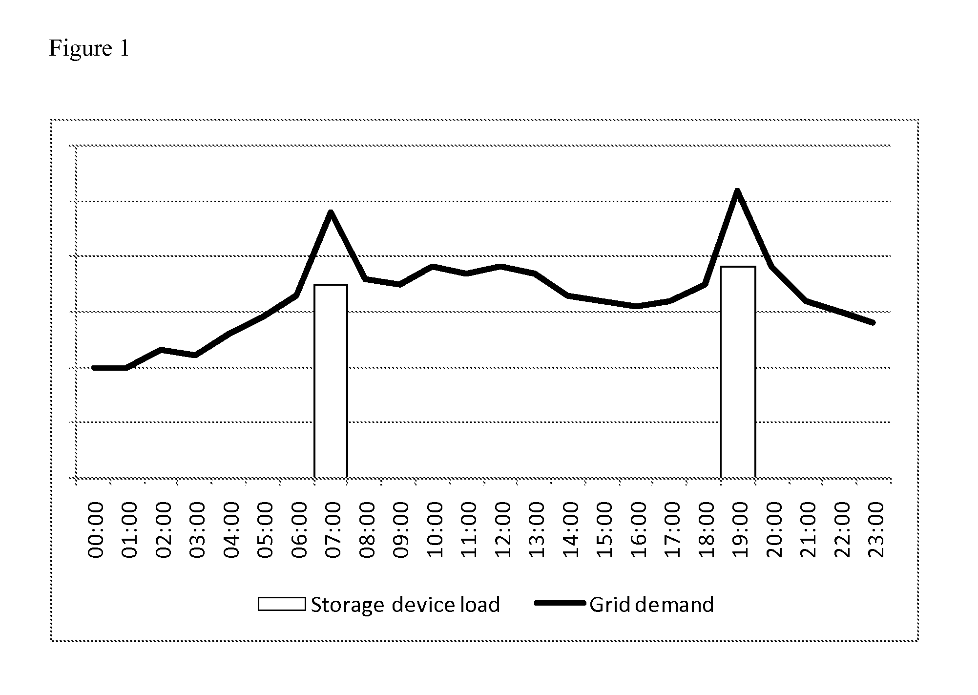
FIELD OF THE INVENTION[0001]The present invention relates to cryogenic energy storage systems, and particularly to methods for capturing thermal energy, such as cold energy and re-using that captured energy.BACKGROUND OF THE INVENTION[0002]Electricity transmission and distribution networks (or grids) must balance the generation of electricity with the demand from consumers. This is normally achieved by modulating the generation side (supply side) by turning power stations on and off, and running some at reduced load. As most existing thermal and nuclear power stations are most efficient when run continuously at full load, there is an efficiency penalty in balancing the supply side in this way. The expected introduction of significant intermittent renewable generation capacity, such as wind turbines and solar collectors, to the networks will further complicate the balancing of the grids, by creating uncertainty in the availability of parts of the generation fleet. A means of storing ...

Claims


Application Information

Patent Timeline
Patent Type & Authority Applications(United States)
IPC IPC(8): F17C7/02
CPCF17C7/02F02C1/04F01K3/00F17C7/04F25J1/0012F25J1/0035F25J1/0037F25J1/004F25J1/0045F25J1/0202F25J1/0251F25J1/0264F25J1/0288F25J2205/24F25J2210/06F25J2235/02F25J2240/90F25J2270/06F25J1/0228Y02E60/16F01K25/10F02C6/14F02C7/10F02C6/16Y02E60/14
Inventor MORGAN, ROBERTNELMES, STUARTCASTELLUCCI, NICOLABRETT, STEPHEN GARETH
Owner HIGHVIEW ENTERPRISES LTD
Learn More