Check patentability & draft patents in minutes with Patsnap Eureka AI!

Segmented Planar Calibration for Correction of Errors in Time of Flight Mass Spectrometers

a mass spectrometer and time-of-flight technology, applied in mass spectrometers, particle separator tube details, separation processes, etc., can solve the problems of additional power supplies, grids and vacuum, relative complex movement stages, etc., and achieve the effect of improving instrument resolution and potential cost savings for reducing tolerance build analyzers

Active Publication Date: 2014-09-04
MICROMASS UK LTD
View PDF3 Cites 17 Cited by
  • Summary
  • Abstract
  • Description
  • Claims
  • Application Information

AI Technical Summary

Benefits of technology

The patent describes a way to correct distortion in a mass analyzer caused by various effects including tilting, bowing, rippling, and flatness. The approach involves finding a tilted component or gimbal within the analyzer and using it to correct for the distortion. This method is more effective compared to using a gimbal or tiltable detector.

Problems solved by technology

However, this requires a relatively complex movement stage which must be operated under vacuum conditions.
It is known to use electrical means to attempt to correct for loss of mass spectral resolution but such approaches require additional power supplies, grids and vacuum feed throughs.

Method used


Image

  • Segmented Planar Calibration for Correction of Errors in Time of Flight Mass Spectrometers
  • Segmented Planar Calibration for Correction of Errors in Time of Flight Mass Spectrometers
  • Segmented Planar Calibration for Correction of Errors in Time of Flight Mass Spectrometers

Examples


Embodiment Construction

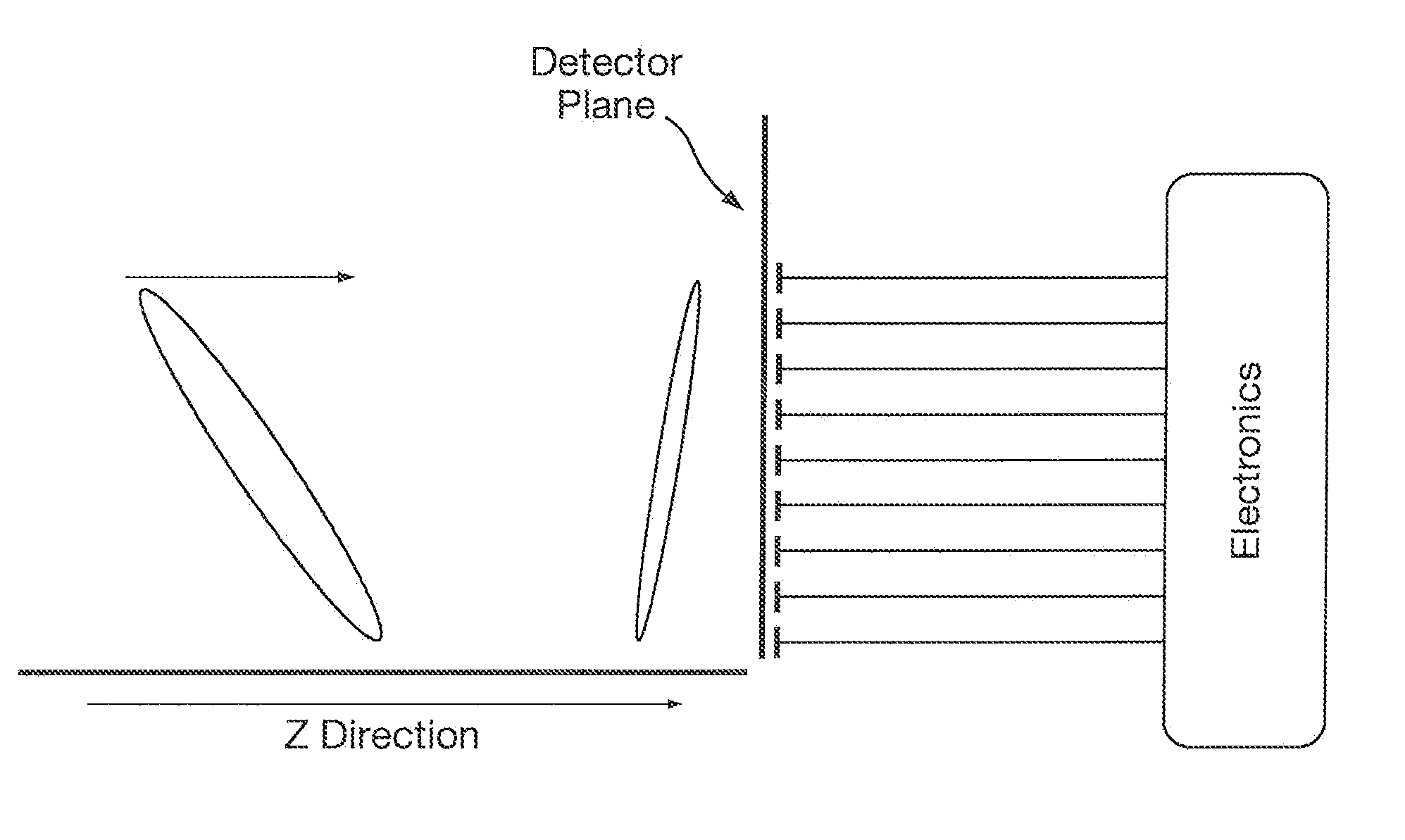
[0071]It is well known to those skilled in the art of Time of Flight design that one of the factors that limit the resolution of Time of Flight mass spectrometers is the optical alignment between the various components that make up the Time of Flight mass analyzer. This is especially important in orthogonal acceleration Time of Flight (“oa-TOF”) mass spectrometers which commonly comprise of a set of parallel electric field regions which are delineated by a series of meshes or grids with precise mechanical separation. The location of these optical components are known as the principal planes of the Time of Flight mass spectrometer. Particular attention is paid to the parallelism and flatness of the principal planes which are commonly aligned to within a few microns to ensure high mass resolution.

[0072]In 1955 Wiley and McLaren set out the mathematical formalism upon which subsequent Time of Flight instruments have been designed. Reference is made to: “Time-of-Flight Mass Spectrometer...


PUM


Abstract

An ion detector system for a mass spectrometer is disclosed comprising an ion detector comprising an array of detector elements. The ion detector system is arranged to correct for tilt and non-linear aberrations in an isochronous plane of ions. The ion detector system generates separate first mass spectral data sets for each detector element and then applies a calibration coefficient to each of the first mass spectral data sets to produce a plurality of second calibrated mass spectral data sets. The plurality of second calibrated mass spectral data sets are then combined to form a composite mass spectral data set.

Description

CROSS REFERENCE TO RELATED APPLICATION[0001]This application claims priority from and the benefit of U.S. Provisional Patent Application Ser. No. 61 / 488,279 filed on 20 May 2011 and United Kingdom Patent Application No. 1108082.7 filed on 16 May 2011. The entire contents of these applications are incorporated herein by reference.[0002]The present invention relates to an ion detector, a mass spectrometer, a method of detecting ions and a method of mass spectrometry.BACKGROUND TO THE INVENTION[0003]U.S. Pat. No. 5,654,544 and U.S. Pat. No. 5,847,385 disclose using electrostatic deflectors in a Time of Flight mass spectrometer to steer ions into a detector positioned at the end of the drift region. The detector assembly is tilted in relation to the steered ion beam in a manner which improves mass spectral resolution.[0004]The Applicants have developed a mechanical gimbal which may be used to correct for loss of mass spectral resolution. However, this requires a relatively complex movem...

Claims


Application Information

Patent Timeline
IPC IPC(8): H01J49/00H01J49/02
CPCH01J49/02H01J49/0009H01J49/025H01J49/40H01J49/0036H01J49/401
Inventor LANGRIDGE, DAVID J.WILDGOOSE, JASON LEE
Owner MICROMASS UK LTD
Features
  • R&D
  • Intellectual Property
  • Life Sciences
  • Materials
  • Tech Scout
  • Unparalleled Data Quality
  • Higher Quality Content
  • 60% Fewer Hallucinations
Learn More