

Method and system for controlling switching frequency of a doubly-fed induction generator (DFIG)
a technology of double-fed induction generator and switching frequency, which is applied in the control system, control of electric generators, ac network circuit arrangements, etc., can solve the problems of changing the frequency of power generated, the physical size and cost of producing such filters is significant, and the size and cost of these filters are also significant. , to achieve the effect of reducing harmonic attenuation filter size requirements, effective increasing switching frequency, and less expensiv
- Summary
- Abstract
- Description
- Claims
- Application Information
AI Technical Summary
Benefits of technology
Problems solved by technology
Method used
Image

Examples
Embodiment Construction
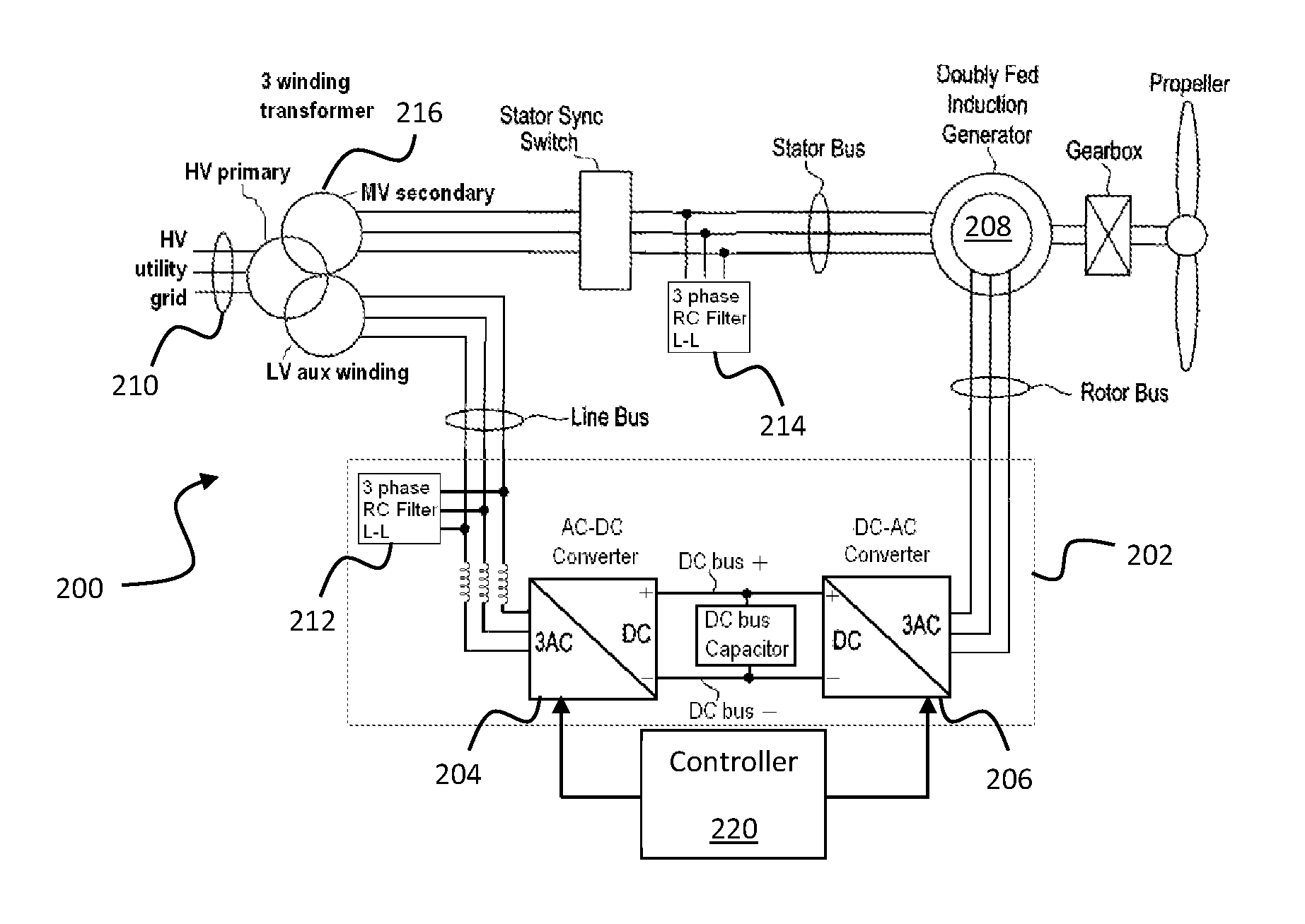
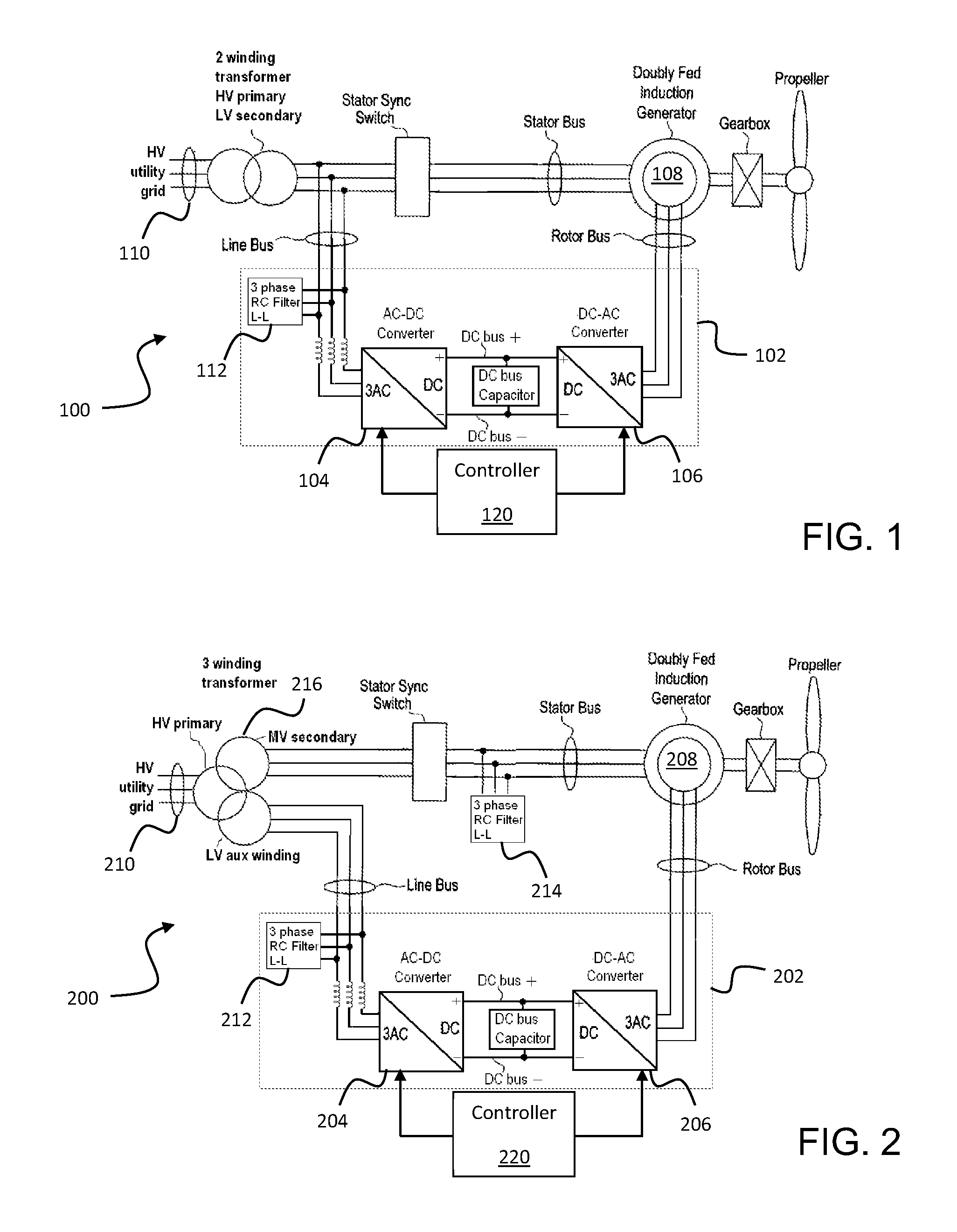
[0022]As discussed in the Summary of the Subject Matter section, the present subject matter is particularly concerned with methods and systems for controlling variable speed generators coupled to a power distribution grid.
[0023]Reference now will be made in detail to embodiments of the invention, one or more examples of which are illustrated in the drawings. Each example is provided by way of explanation of the invention, not limitation of the invention. In fact, it will be apparent to those skilled in the art that various modifications and variations can be made in the present invention without departing from the scope or spirit of the invention. For instance, features illustrated or described as part of one embodiment can be used with another embodiment to yield a still further embodiment. Thus, it is intended that the present invention covers such modifications and variations as come within the scope of the appended claims and their equivalents.
[0024]In accordance with the presen...
PUM
 Abstract
Description
Claims
Application Information