
Low Inductance Laser Diode Bar Mount

Active Publication Date: 2014-09-04
OBZERV TECH
View PDF3 Cites 0 Cited by
  • Summary
  • Abstract
  • Description
  • Claims
  • Application Information

AI Technical Summary

Benefits of technology

The patent text describes a method for mounting driver and laser bar components on a heat sink base using clamps. This avoids the need for soldering, which could induce stress in the laser bar. The second electrical connection is designed to allow for lengthwise displacement to account for variations in the exact positioning of the driver. This is achieved by providing a sheet of electrically conductive material with a narrow fold that allows for movement of the driver connection portion lengthwise while securing the laser bar. This design maintains a relatively small loop surface area while giving added flexibility. The technical effects of this method include improved reliability, reduced stress, and improved flexibility while maintaining low inductance.

Problems solved by technology

One limitation of former mount arrangements was due to the high inductance of the electrical connection circuit, which limited the ability to obtain satisfactory fast rise time and fall time.

Method used


Image

  • Low Inductance Laser Diode Bar Mount
  • Low Inductance Laser Diode Bar Mount
  • Low Inductance Laser Diode Bar Mount

Examples


Embodiment Construction

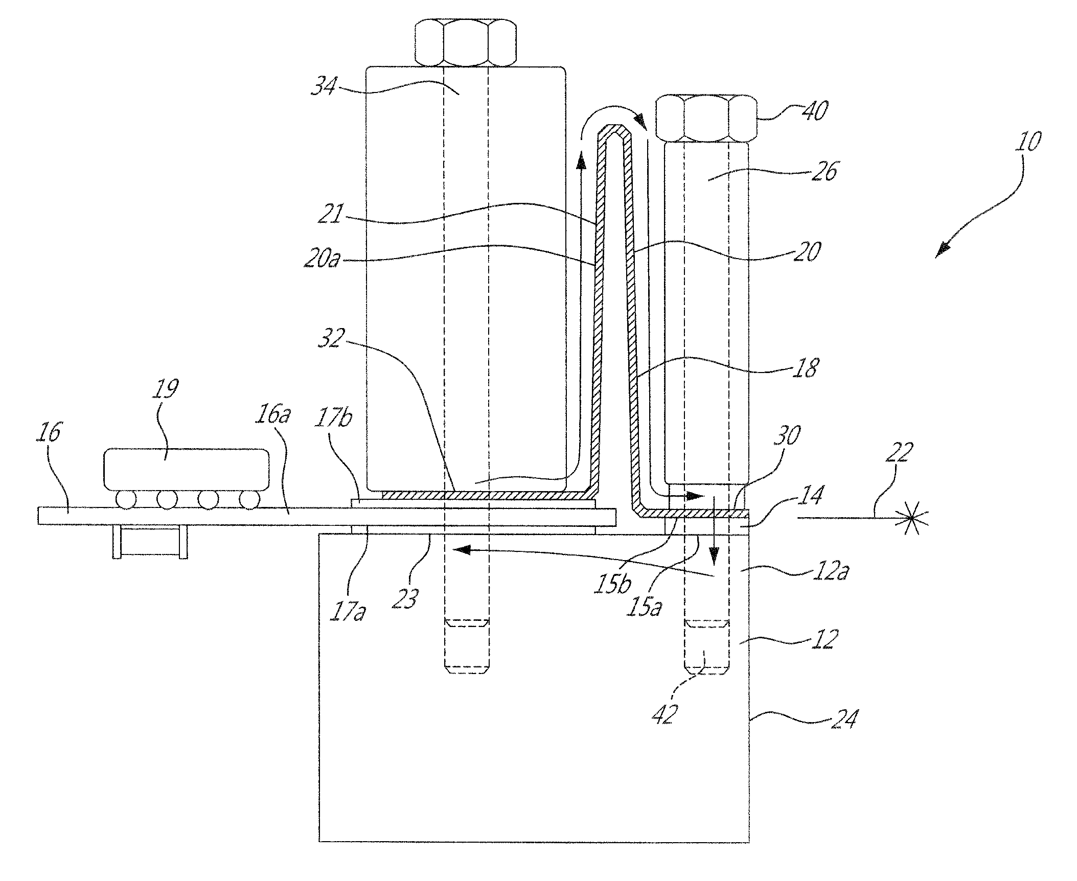
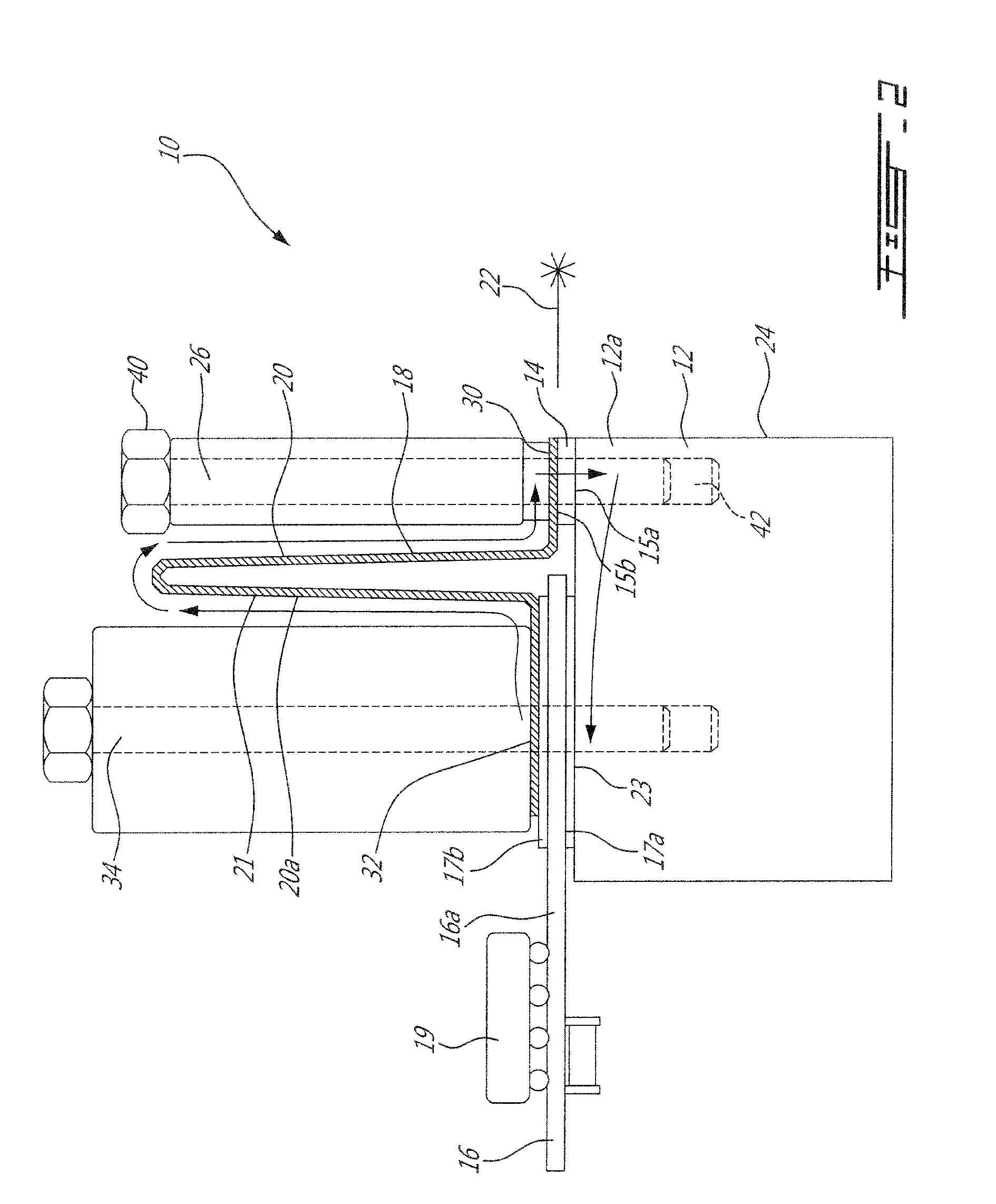
[0022]FIG. 2 schematically shows an example of a low-inductance laser mount arrangement 10. In this example, a heat sink base 12, which is made of a material which has both high thermal conductivity and low electrical resistivity, receives both a laser bar 14 and a driver 16. In this case, the driver 16 is in the form of a printed circuit board 16a having control electronics 19 for driving the laser bar in pulsed mode and electrical contacts 17a, 17b of the driver on opposite sides thereof, and the laser bar 14 also has electrical contacts 15a, 15b on opposite sides thereof. Corresponding electrical contacts 15a, 17a of both the laser bar 14 and the driver 16 are connected with the heat sink base 12 which acts as a first electrical connection 12a therebetween. A second electrical connection 18 configured in a manner to generate low inductance, is connected with the both the laser bar 14 and the driver 16 on the side opposite the heat sink base 12. In this particular case, the second...


PUM

PropertyMeasurementUnit
Poweraaaaaaaaaa
Electrical inductanceaaaaaaaaaa

Abstract

The laser mount arrangement can have a laser bar and a driver positioned adjacent to one another and secured against a connection face of a heat sink base. The heat sink base is connected to and forms a first electrical connection between the laser bar and the driver. A second electrical connection is also provided between the laser bar and the driver opposite the heat sink base, which can be in the form of a flexible metal sheet with a narrow upward fold. This arrangement can provide a low inductance path for the current.

Description

BACKGROUND[0001]Laser diode bars (hereinafter referred to as laser bars for simplicity) are well known electro-optical devices which typically consist of a bar of adjacent laser diodes. A laser bar has a P and a N electrical contacts on respective opposite faces to power the laser diodes via electrical connections.[0002]Although former laser bar mounts were satisfactory to a certain degree, there remained room for improvement in the manner to mount the laser diode bar to a heat sink and to power it. For instance, the electrical connection circuit between the laser bar and the controlling electronics of former laser bar mounts had an inductance satisfactory when operating in continuous wave or quasi continuous wave modes, but there remained room for improvements when operating un pulse mode.SUMMARY[0003]Attempts to operate laser diode bars using former mount arrangements in pulse mode met with several limitations. One feature which is sought in pulse laser mode application is fast ri...

Claims


Application Information

Patent Timeline
IPC IPC(8): H01S5/022H01S5/023
CPCH01S5/02236H01S5/02438H01S5/02469H01S5/06216H01S5/4025Y10T29/49947Y10T29/49826H01S5/02365H01S5/02345H01S5/0233H01S5/023H01S5/0235
Inventor DEMERS, LOUISGODIN, JACQUESGRENIER, MARTIN
Owner OBZERV TECH
Learn More