Automated sanitation

Active Publication Date: 2011-05-10
VWS UK
View PDF15 Cites 8 Cited by
  • Summary
  • Abstract
  • Description
  • Claims
  • Application Information

AI Technical Summary

Benefits of technology

[0008]It is an object of the present invention to provide a method for overcoming these disadvantages.

Problems solved by technology

In other circumstances, the cleaning procedure or cycle may require the addition of a further amount or amounts of substance such as a cleaning chemical, either as part of the procedure or cycle, or because an insufficient amount of the substance was initially added, either unintentionally, or unexpectantly.

Method used


Image

  • Automated sanitation
  • Automated sanitation
  • Automated sanitation

Examples


example

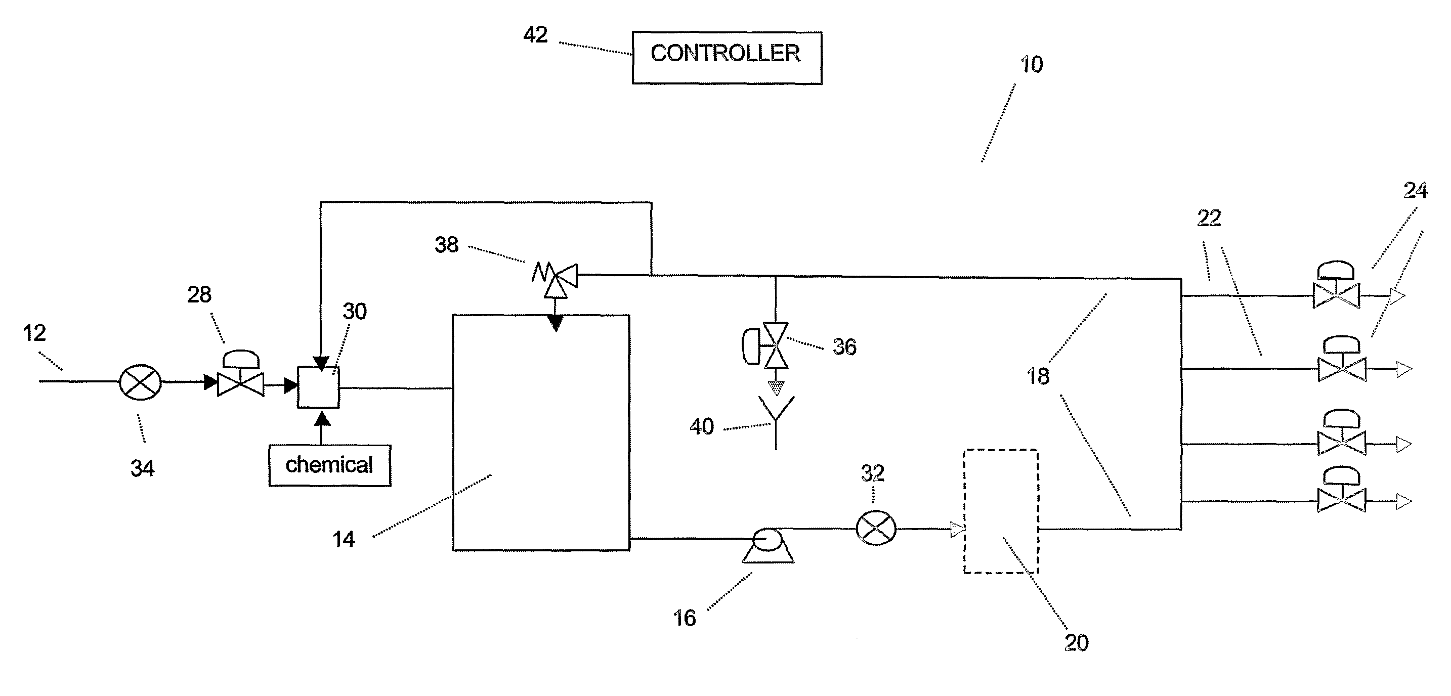
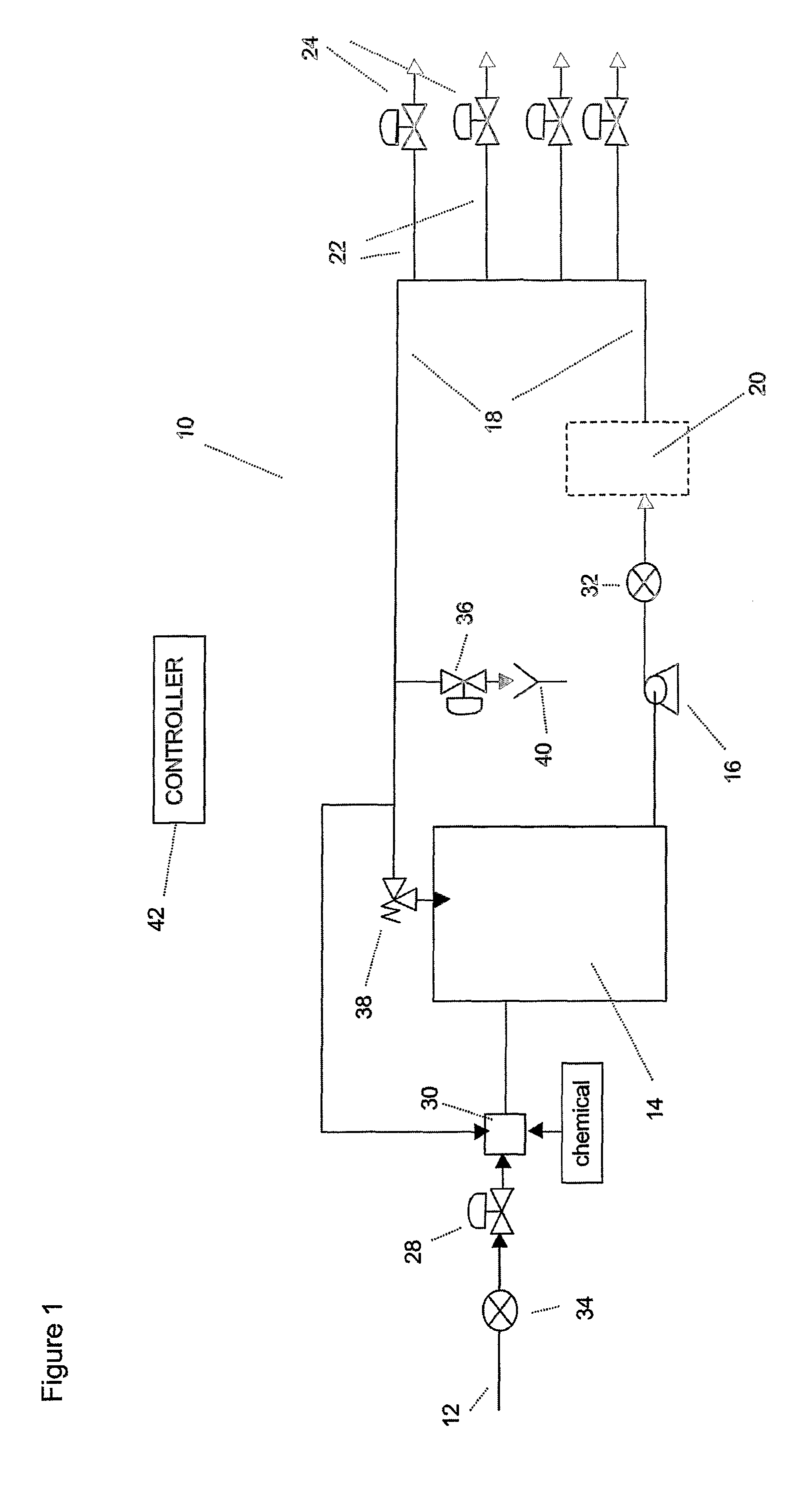
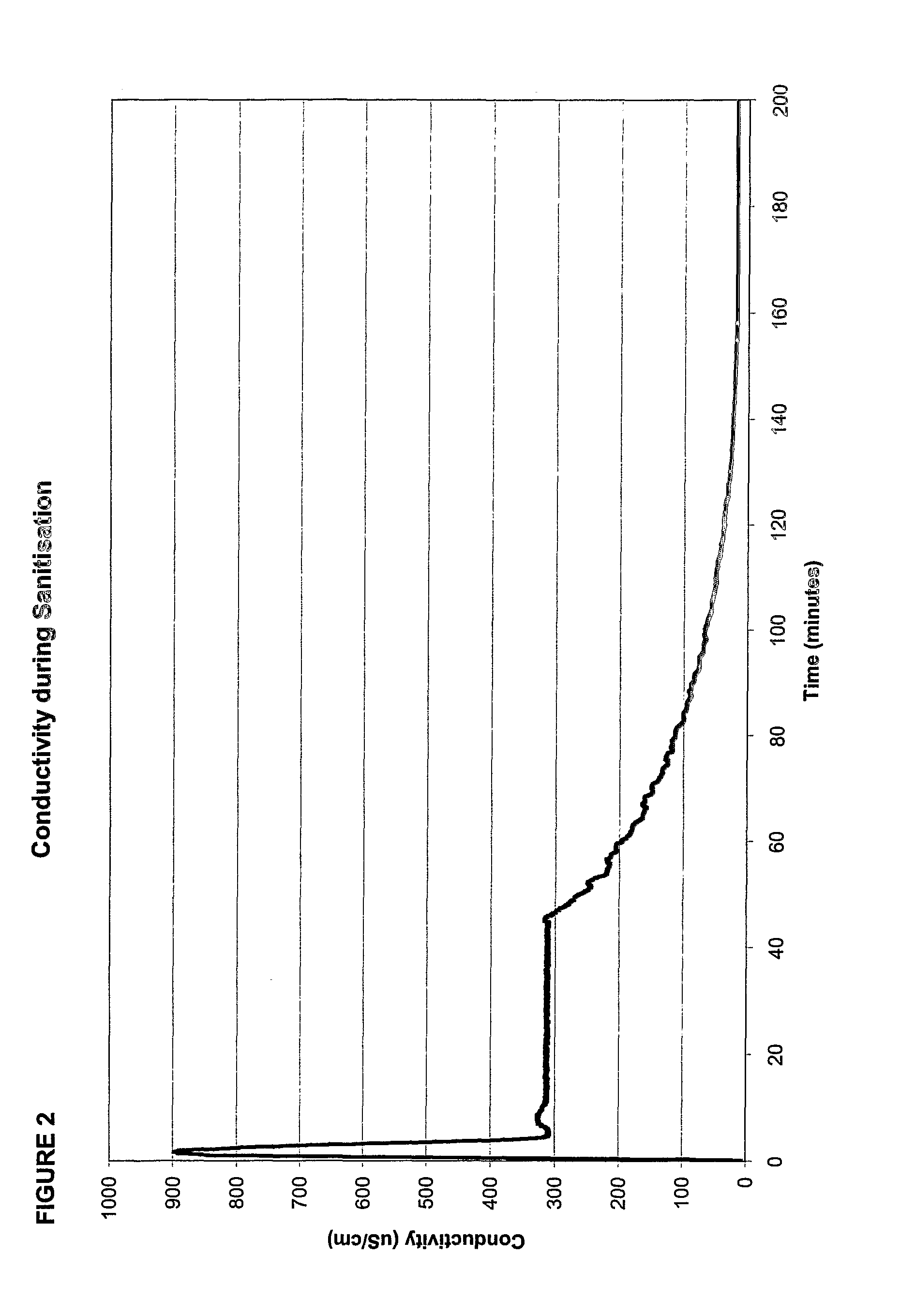
[0052]FIG. 2 is a sanitisation profile as recorded by apparatus based on that shown in FIG. 1, containing a water purification system with a 350 liter reservoir, a recirculation pump and a ringmain. In-line conductivity sensors as known in the art were installed in the feedwater to the reservoir and in the ringmain. The sensors provided a signal to a control board containing an enhanced FLASH microcontroller.

[0053]The amount of water in the reservoir was lowered to 40 liters and a sanitisation solution of 0.9 litre of 22% hydrogen peroxide and 4.5% peroxyacetic acid was added to the chemical transfer port. The solution was allowed to recirculate for a period of 45 minutes.

[0054]The controller recorded the conductivity profile of the solution being recirculated as shown in FIG. 2. The controller was able to compare the peak conductivity as the sanitant enters the recirculation loop (900 μS / cm) with limits set in its memory. This initial peak may also be integrated to provide an amoun...


PUM

PropertyMeasurementUnit
peak conductivityaaaaaaaaaa
conductivityaaaaaaaaaa

Abstract

An automated method for determining the cleaning operation of a water treatment or water distribution apparatus or system to which one or more substances are added, the method comprising the steps of: (a) conducting one or more measurements of a property of the or an added substance; (b) comparing the property measurement s) from step (a) with at least one reference value for that property; and (c) determining when the comparison in step (b) is within, above or below a pre-determined range or level for that property. The determination in step (c) can consider whether the cleaning operation has been successfully carried out. The present invention automates and therefore optimizes the cleaning operation of the water treatment or distribution apparatus or system such that expensive periods of non-operation during sanitization or cleaning are minimized both in terms of frequency and duration.

Description

FIELD OF THE INVENTION[0001]The present invention relates to an automated method for verifying the cleaning of a water treatment or distribution apparatus, particularly but not exclusively sanitisation of such apparatus.BACKGROUND[0002]In the field of water treatment and distribution for applications such as laboratories, medical, clinical, research, manufacturing and others, it is important that the water treatment and distribution system is maintained either free from microbial contamination, or that the contamination is controlled to below a specified level.[0003]One way of carrying this out is by thermal means. However, the high temperatures involved require the use of expensive components which have high fabrication and finishing costs, remembering also the high purity requirements. Many water treatment and distribution units, apparatus and other such type equipment can now be made from or use much less expensive plastic components. This greatly reduces cost, but means that the...

Claims


Application Information

Patent Timeline
Patent Type & Authority Patents(United States)
IPC IPC(8): B08B3/04B08B9/093C02F1/00C02F1/32C02F1/42C02F1/44C02F1/72
CPCC02F1/008C02F1/32C02F1/42C02F1/444C02F1/722C02F2301/046C02F2209/003C02F2209/005C02F2209/05C02F2209/06C02F2209/001C02F2303/14C02F2303/20
Inventor MORTIMER, ALAN DENTONUNDERWOOD, LEE
Owner VWS UK
Why Eureka
Try Eureka