
Lubricating oil supply device

a technology of lubricating oil and supply device, which is applied in the direction of rotary clutches, fluid couplings, gearings, etc., can solve the problems of increasing the number of components and increasing so as to reduce the loss of transmission, increase the number of components, and increase the size of the device

Active Publication Date: 2014-09-11
AISIN AW CO LTD
View PDF4 Cites 8 Cited by
  • Summary
  • Abstract
  • Description
  • Claims
  • Application Information

AI Technical Summary

Benefits of technology

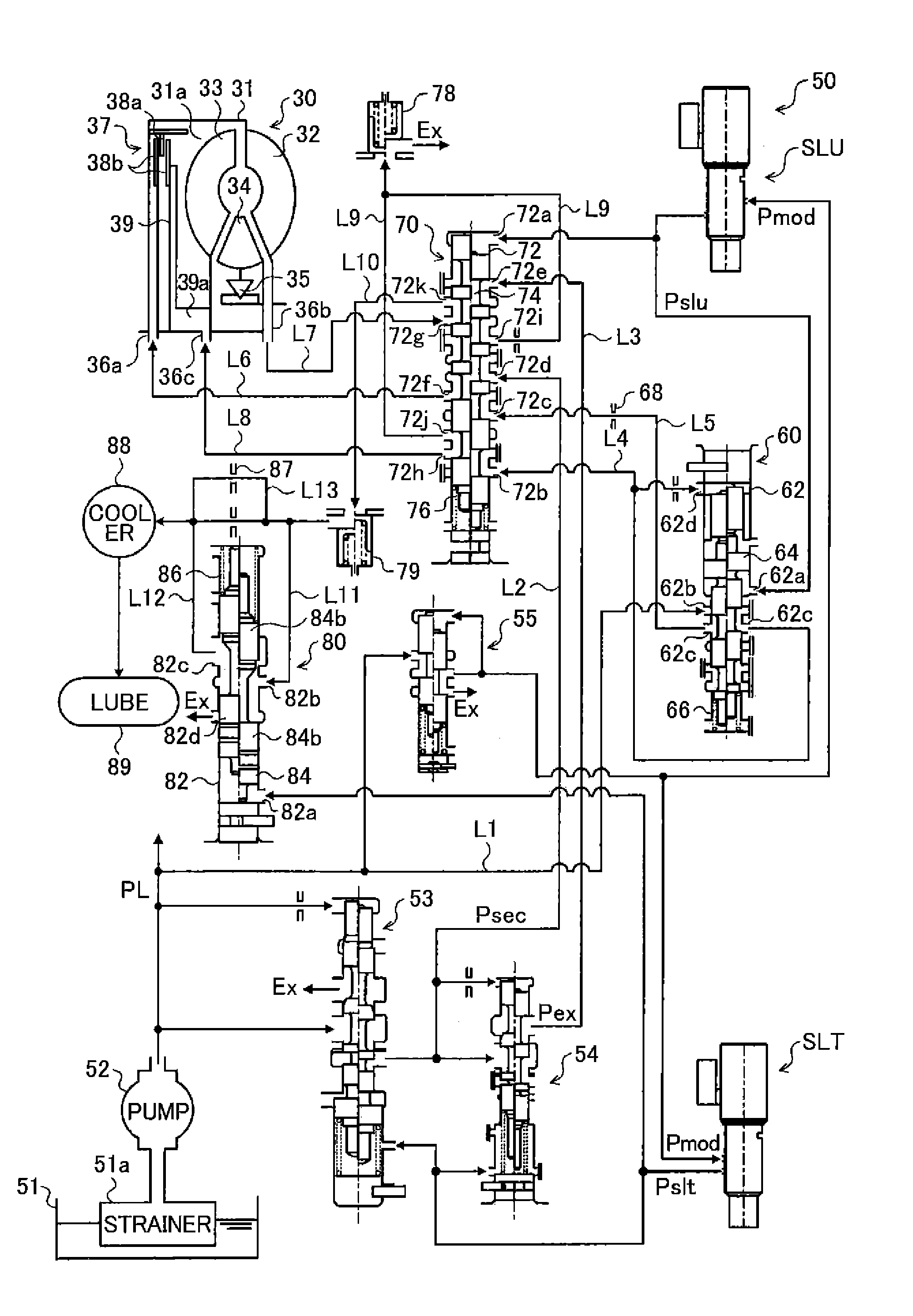
The present invention relates to a lubricating oil supply device for transmissions. The device includes a line pressure generation valve, a signal pressure output valve, and a switching valve. The signal pressure output valve controls the actuation of the line pressure generation valve and the switching valve, which supplies lubricating oil to the object to be lubricated. The device can optimize the flow rate of lubricating oil and reduce the size of the device by common use of the signal pressure output valve and actuation of the switching valve in accordance with at least the throttle operation amount or the torque input to the transmission. The switching valve can change the flow rate of lubricating oil with a step, which better matches the amount of lubricating oil required for the object to be lubricated than a design in which the flow rate of lubricating oil is varied linearly with respect to variations in signal pressure. The lubricating oil supply device can switch between a first lubrication mode in which the flow rate of lubricating oil is low and a second lubrication mode in which the flow rate of lubricating oil is high across the step. This allows for optimize lubrication and reduce damage to the transmission.

Problems solved by technology

In the device discussed above, while it is possible to reduce a loss in the transmission by optimizing the amount of oil to be supplied to the object to be lubricated by the lubrication pressure regulator, use of the dedicated electromagnetic valve to drive the lubrication pressure regulator increases the number of components and increases the size of the device.

Method used


Image

  • Lubricating oil supply device
  • Lubricating oil supply device
  • Lubricating oil supply device

Examples


Embodiment Construction

[0025]A preferred embodiment of the present invention will be described below.

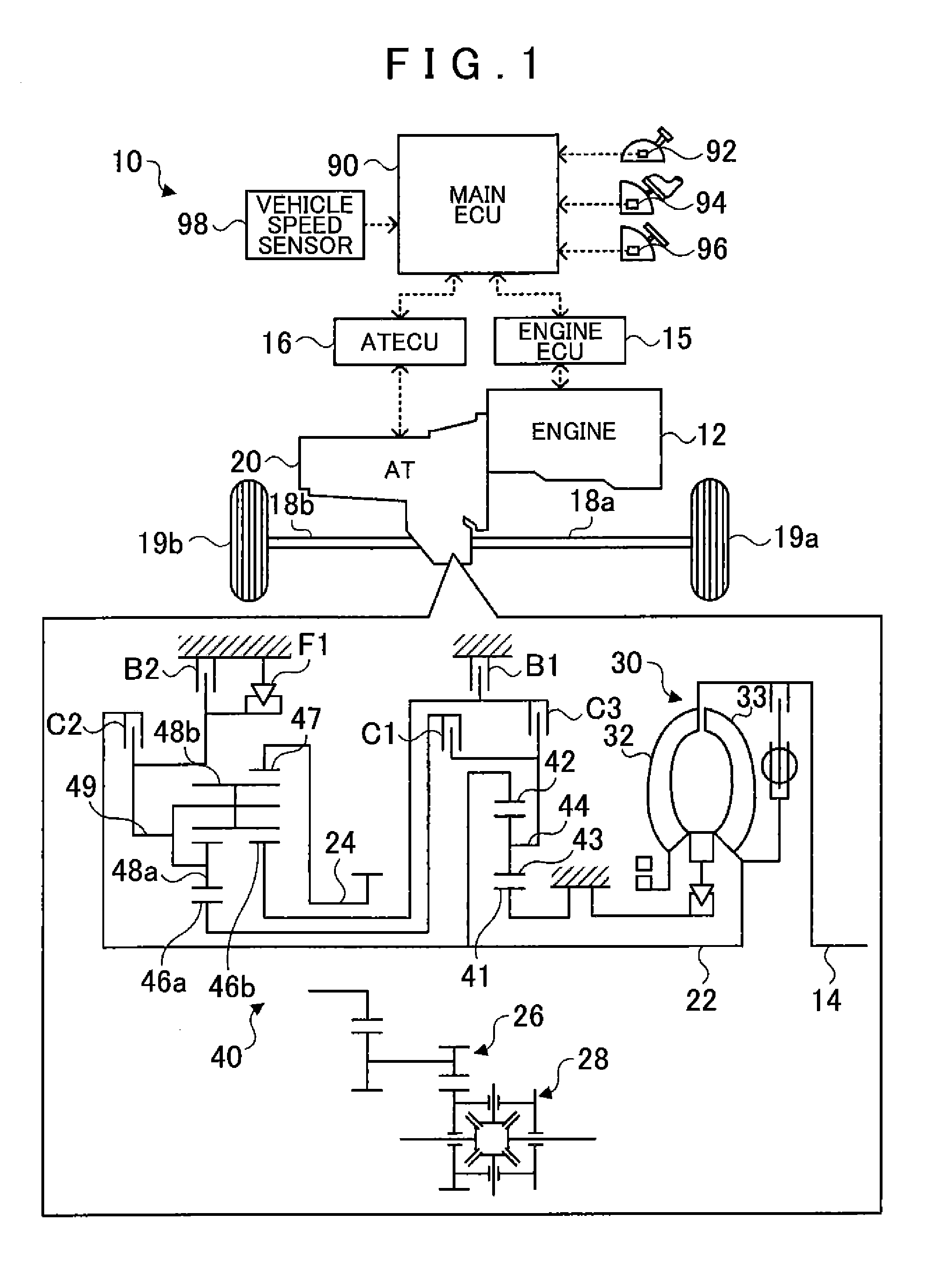
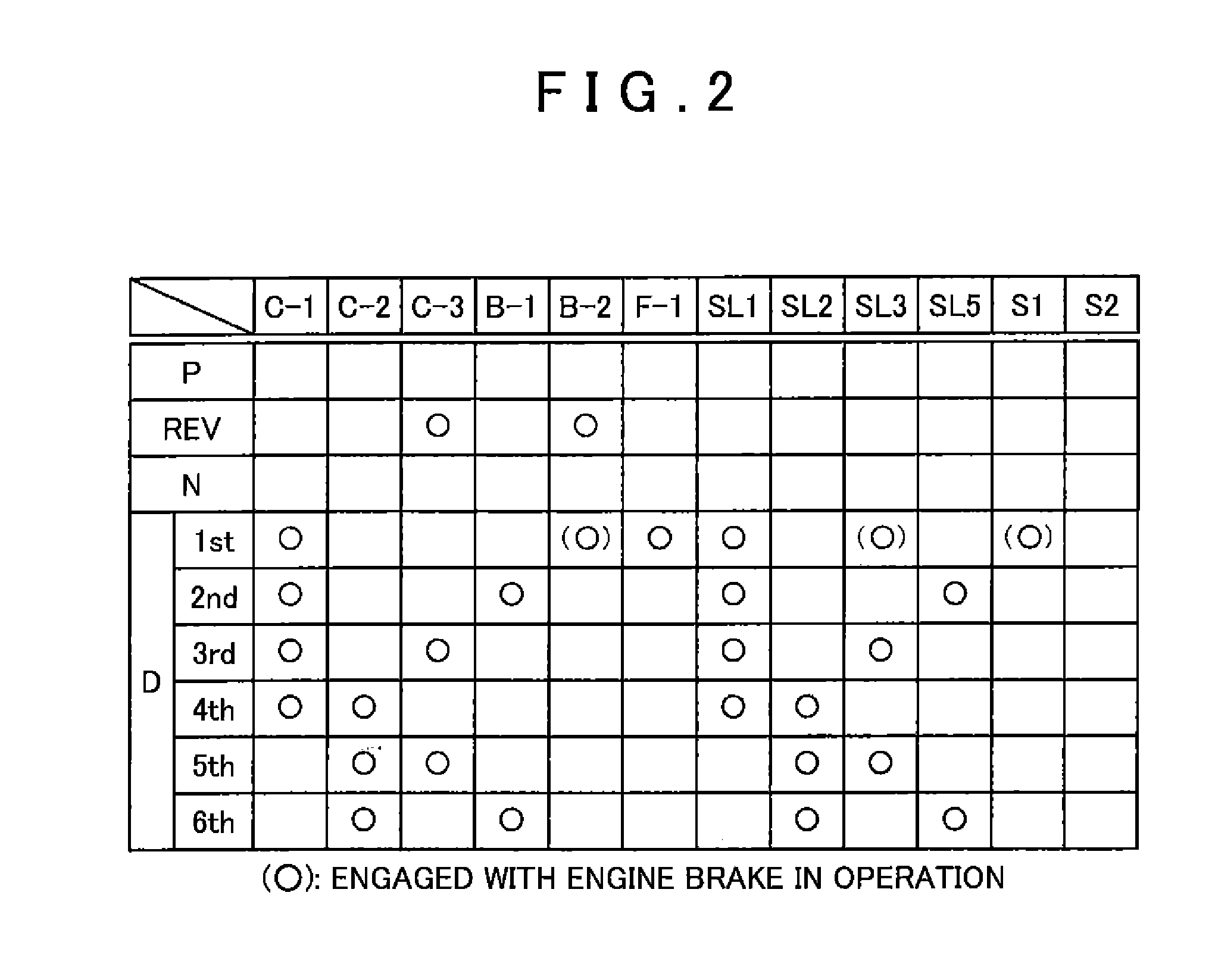
[0026]FIG. 1 is a diagram illustrating a schematic configuration of an automobile 10. FIG. 2 is an operation table of a speed change mechanism 40.

[0027]As illustrated in FIG. 1, the automobile 10 includes: an engine 12 which is an internal combustion engine that outputs power generated by explosive combustion of a hydrocarbon fuel such as gasoline and light oil; an engine electronic control unit (engine ECU) 15 that controls operation of the engine 12; an automatic transmission 20 connected to a crankshaft 14 of the engine 12 and to axles 18a and 18b for left and right wheels 19a and 19b, respectively, to transfer power from the engine 12 to the axles 18a and 18b; an automatic transmission electronic control unit (AT ECU) 16 that controls the automatic transmission 20; and a main electronic control unit (main ECU) 90 that controls the entire vehicle. A shift position SP from a shift position sensor 92 that...


PUM


Abstract

A lubricating oil supply device that supplies hydraulic oil used to actuate a vehicle's transmission. The supply device configured with a pump that generates a hydraulic pressure, and a line pressure generation valve that discharges a part of the hydraulic pressure from the pump as a discharge pressure to generate a line pressure for actuating the transmission. A signal pressure output valve that outputs a signal pressure for actuating the line pressure generation valve in accordance with at least a throttle operation amount or torque input to the transmission. Furthermore, a switching valve that is actuated by the signal pressure from the signal pressure output valve and that supplies lubricating oil input to an input port to the object to be lubricated from an output port with a flow rate of the lubricating oil changed.

Description

TECHNICAL FIELD[0001]The present invention relates to a lubricating oil supply device that supplies hydraulic oil used to actuate a transmission mounted on a vehicle to an object to be lubricated of the transmission as lubricating oil.BACKGROUND ART[0002]Hitherto, there has been proposed a lubricating oil supply device of this type, in which oil leaked from a regulator, which is a part of oil discharged from a hydraulic pump, is supplied to an object to be lubricated of an automatic transmission and an oil cooler (see Patent Document 1, for example). The device includes a lubrication pressure regulator that regulates a pressure (lubrication pressure) to be supplied to the object to be lubricated and that supplies the leaked oil to the oil cooler, and the lubrication pressure regulator is driven by a dedicated electromagnetic valve. Specifically, the electromagnetic valve is controlled such that the amount of oil to be supplied to the object to be lubricated is reduced and the amount...

Claims


Application Information

Patent Timeline
IPC IPC(8): F16H41/30F16H45/02F16N25/00
CPCF16H41/30F16H2045/0215F16H45/02F16N25/00F16H57/0446F16H61/0021F16H61/0206F16H2061/0037F16H61/143Y10T137/8601
Inventor KUTSUBO, HIROYUKIKOJIMA, KAZUKISHIMIZU, TETSUYATSUCHIDA, KENICHIISHIKAWA, KAZUNORI
Owner AISIN AW CO LTD
Learn More