Current measurement

a current measurement and current technology, applied in the direction of reference comparison, moving-iron instruments, instruments, etc., can solve the problems of inaccuracy in determination of load drawn current signal, transfer function of measurement arrangement is liable to be unknown, etc., to achieve accurate power measurement, accurate power measurement, and accurate current measurement.

Active Publication Date: 2014-09-11
ANALOG DEVICES INT UNLTD
View PDF6 Cites 64 Cited by
  • Summary
  • Abstract
  • Description
  • Claims
  • Application Information

AI Technical Summary

Benefits of technology

[0033]The signal source may be configured to change an amplitude of the reference input signal. Changing an amplitude of the reference input signal may be advantageous where the load drawn current signal changes between large and small values, e.g. to achieve a compromise between accuracy and power consumption. In certain applications, such as in domestic supply of electricity, the load drawn current signal may vary between 0 and 50 Amps. Changing an amplitude of the reference input signal may also be advantageous to trade-off power consumption and time involved in acquiring data for determining different transfer functions. For example acquisition apparatus may operate at a higher rate during factory calibration to provide for faster determination of transfer function to the required accuracy. By way of another example the acquisition apparatus may operate at a lower rate when monitoring for change in transfer function for diagnostic purposes to thereby save on power consumption. Where the reference input signal comprises different frequency components at any one time, amplitudes of the different frequency components may differ from each other. The signal source may be configured to generate such a reference input signal.
[0034]The current measurement apparatus may be configured to change a direction in which the reference input signal is passed through the measurement arrangement. More specifically the current measurement apparatus may comprise a switch arrangement which is operative to select an end of the measurement arrangement to which the reference input signal is applied. The current measurement apparatus may be configured such that the signal source forms a signal source circuit path with a current sensor comprised in the measurement arrangement and acquisition circuitry comprised in the measurement arrangement forms an acquisition circuit path with the current sensor, the signal source circuit path and the acquisition circuit path being separate. Separation of the two paths from each other may reduce the likelihood of parasitic components present in the acquisition circuit path having an adverse effect on the operation of the reference input signal. For example separation of the two paths may avoid a voltage drop being developed by the reference input signal across parasitic resistance in the acquisition circuit path which would otherwise compromise measurement accuracy.
[0044]The current measurement apparatus may comprise a measurement assembly comprising the measurement arrangement, the at least one conductor and the signal source conductor. The measurement assembly may be configured to maintain the spatial separation of at least part of the measurement arrangement, such as a coil of a current sensor, the at least one conductor and the signal source conductor amongst each other to within a predetermined limit. Maintaining spatial separation to within a predetermined limit may provide for more accurate measurement of the current signal, e.g. by reducing misalignment of magnetic fields. The spatial separation may be maintained by the measurement arrangement, the at least one conductor and the signal source conductor being bonded in the measurement assembly or by the measurement assembly being configured to hold the measurement arrangement at least in part, the at least one conductor and the signal source conductor.
[0062]An approach to addressing the problem involves increasing the power of the reference input signal to thereby improve the ratio of the reference output signal to the load output signal. However this approach may result in power consumption being increased to an unacceptable level. An alternative approach to addressing the problem springs from an appreciation that the load output signal may either be already determined or may be determinable. The alternative approach may involve subtracting the load output signal from the measured signal to thereby leave the reference output signal and whatever noise there may be, such as noise generated by the processing electronics. The current measurement apparatus may therefore be configured to determine the load output signal and to subtract the load output signal from a signal measured by the measurement arrangement to thereby provide a reference output signal. Furthermore the current measurement apparatus may be configured to determine a transfer function or a change in the transfer function of the measurement arrangement in dependence on the reference output signal. The current measurement apparatus may be configured to determine the load drawn current in dependence on the determined transfer function or to adjust the determination of load drawn current in dependence on the change of the transfer function or on a change in the reference input signal itself. The earlier described approaches to separation of the reference output signal, such as the FFT approach, may be employed in addition to the present subtraction approach to at least one of address noise and provide for improved determination, e.g. with regards to accuracy, of the transfer function or the change in the transfer function.
[0067]According to a yet further embodiment the signal source may be configured to modulate the reference input signal before its application to the measurement arrangement. According to this embodiment the reference output signal may be extracted in dependence on operation of a single measurement arrangement in contrast to the previous embodiments which use two measurement arrangements. Modulation may be by way of a form of Return To Zero (RTZ) approach or the like. Modulation may be aligned to the fundamental frequency of the load drawn signal in frequency (for example, changed at a rate that is a multiple of the load drawn signal frequency) and or phase (for example, aligned to the zero crossing point of the load drawn signal or the line voltage). Additionally or alternatively modulation may comprise sub-harmonic modulation where at least one characteristic of the reference input signal is different during different cycles of the load drawn current signal. The processing apparatus may be operative to process and if required store information from different cycles of the load drawn current signal to extract information from the modulation. Furthermore the processing apparatus may comprise a demodulator which is operative to separate the signal acquired from the measurement arrangement into a first signal comprising the reference output signal and the load output signal and a second signal comprising the load output signal and substantially lacking the reference output signal. To aid modulation and demodulation it may be beneficial for the signal source and signal acquisition circuitry to be synchronous. In addition to the first and second signals having a difference in reference signal content, they may contain largely the same spectral content as the load output signal although with different phase relationships because they are demodulated through the same chain. After alignment and / or equalisation the processing apparatus may then be operative to subtract the second signal from the first signal to thereby obtain the reference output signal. The processing apparatus may be operative to only use part of the information available, for example in a particular relative time or phase of the load drawn current signal. The processing apparatus may be operative to filter or discard values that are deemed by operation of the processing apparatus to be outside a normal operation range, to handle spurious noise or to handle changing load conditions. The present embodiment offers the advantage over the previously described embodiments of relying on one measurement arrangement. The present embodiment therefore offers the prospect of lower power consumption and lower cost than the previously described embodiments.

Problems solved by technology

However the transfer function of the measurement arrangement is liable to be unknown at point of assembly due to manufacturing tolerances.
Also the transfer function is liable to change over time and thereby give rise to inaccuracy in determination of the load drawn current signal.

Method used


Image

  • Current measurement
  • Current measurement
  • Current measurement

Examples


first embodiment

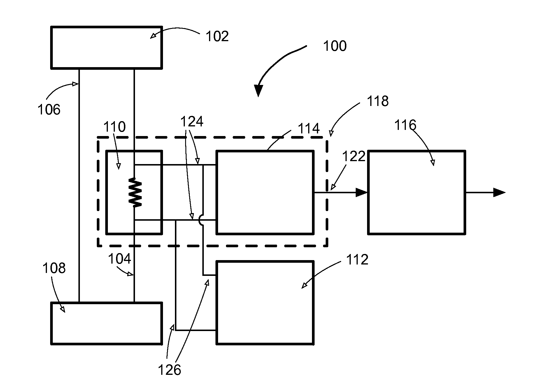
[0108]current measurement apparatus 100 having a first form of electrical connection to a shunt resistor is shown in FIG. 1A. The current measurement apparatus 100 forms part of an electricity consumption meter (not shown) installed at a point of supply to residential or business premises. A single phase mains alternating current electricity source 102 with live 104 and neutral 106 supply wires are shown in FIG. 1A. Energy consuming apparatus at the residential or business premises is represented by a load 108. The current measurement apparatus 100 comprises a shunt resistor 110 (which constitutes a current sensor) in the live supply wire 104 in series with the load 108 between the load and the electricity supply 102. The shunt resistor 110 presents a low value of resistance, such as a resistance of 1 mΩ. The shunt resistor 110 is formed from a length of electrical wire, a length of conductive track on a printed circuit board, a discrete component, a conductor comprised in an integr...

second embodiment

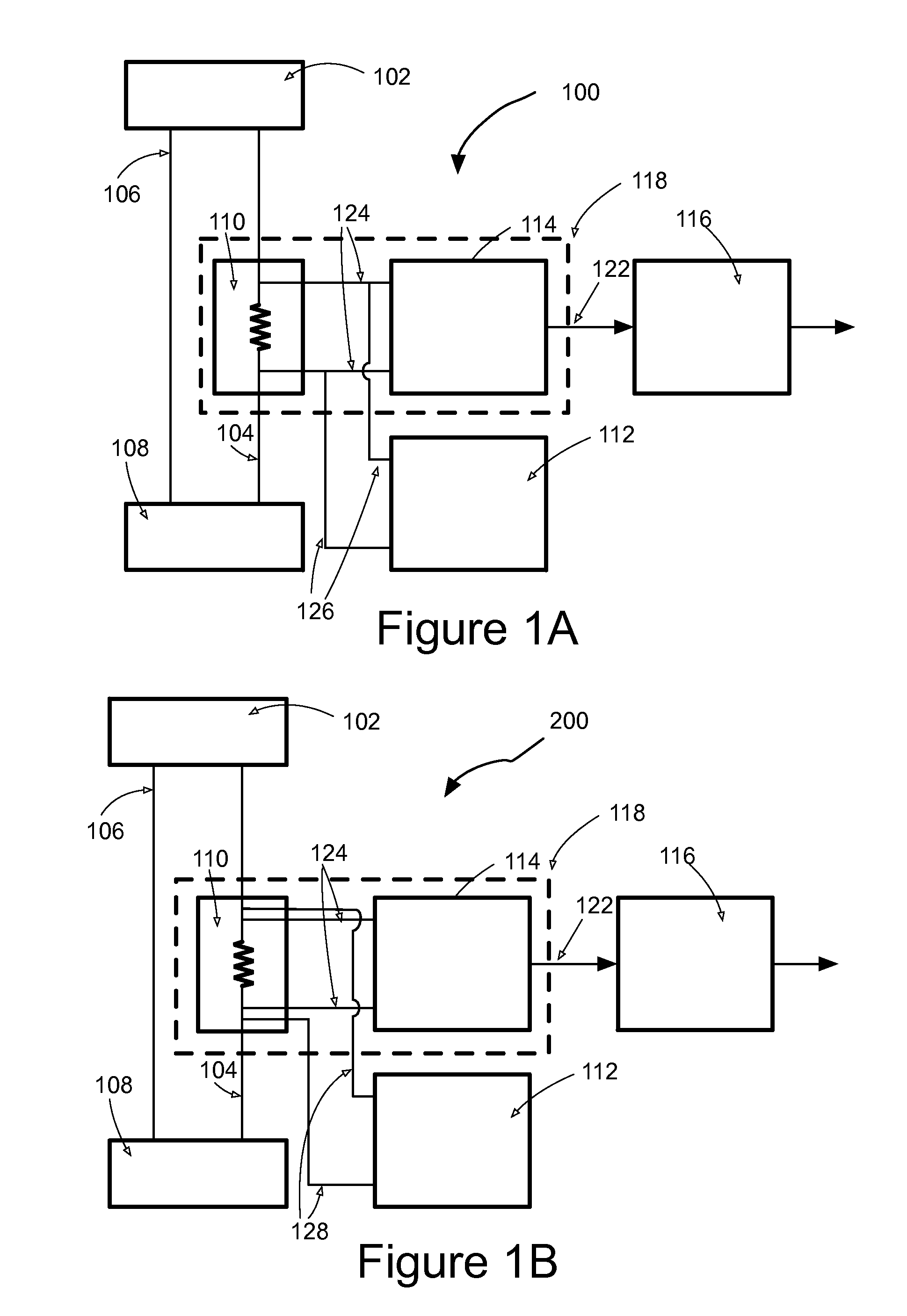
[0112]current measurement apparatus 200 having a second form of electrical connection to the shunt resistor is shown in FIG. 1B. Features in common with the current measurement apparatus 100 of FIG. 1A are indicated by the same reference numerals and the reader's attention is directed to the description provided above with reference to FIG. 1A for a description of the form and function of such common features. A first pair of wires 124 from the voltage measuring apparatus 114 is as per FIG. 1A. A second pair of wires 128 from the signal source 112 establishes an electrical connection by direct connection to opposing ends of the shunt resistor 110 whereby the first and second pairs of wires constitute separate conduction paths between the shunt resistor 110 and each of the voltage measuring apparatus 114 and the signal source 112. The arrangement of FIG. 1B is appropriate where the conduction path between the resistor shunt 110 and the voltage measuring apparatus 114 has parasitic im...

fourth embodiment

[0117]Current measurement apparatus 400 which is configured to measure current in each of a live and neutral wire of an electricity supply is shown in FIG. 3A. The current measurement apparatus 400 comprises a first shunt resistor 402 in the live wire 404 between an ac power source 406 and a load 408 and a second shunt resistor 410 in the neutral wire 412 between the ac power source 406 and the load 408. The current measurement apparatus 400 further comprises a first unit 414 and second unit 416. The first unit 414 comprises a first signal source 418, first voltage measuring apparatus 420 and first signal processing circuitry 422. The second unit 416 comprises a second signal source, second voltage measuring apparatus and second signal processing circuitry. The signal source 418, voltage measuring apparatus 420 and signal processing circuitry 422 of each of the first and second units 414, 416 are configured and operative to determine the load drawn current signals drawn through a r...


PUM


Abstract

The present invention relates to current measurement apparatus 100. The current measurement apparatus 100 comprises a measurement arrangement 110, 114 which is configured to be disposed in relation to a load 108 which draws a current signal, the measurement arrangement being operative when so disposed to measure the load drawn current signal. The current measurement apparatus 100 also comprises a signal source 112 which is operative to apply a reference input signal to the measurement arrangement 110, 114 whereby an output signal from the measurement arrangement comprises a load output signal corresponding to the load drawn current signal and a reference output signal corresponding to the reference input signal. The current measurement apparatus 100 further comprises processing apparatus 116 which is operative to receive the output signal and to make a determination in dependence on the reference output signal and the load output signal, the determination being in respect of at least one of the load drawn current signal and electrical power consumed by the load.

Description

[0001]This application is a Continuation-In-Part of U.S. application Ser. No. 13 / 672,236, filed on Nov. 8, 2012, which claims the priority of U.S. Provisional Application No. 61 / 557,369, filed on Nov. 8, 2011. This application is a Continuation-In-Part of International Application No. PCT / GB2012 / 052251, filed on Sep. 12, 2012, which claims the priority of Great Britain Application No. 1115648.6, filed on Sep. 12, 2011, U.S. Provisional Application No. 61 / 557,369, filed on Nov. 8, 2011, and Great Britain Application No. 1207905.9, filed on May 4, 2012. This application is a Continuation-In-Part of U.S. application Ser. No. 14 / 344,052, which is a 371 national phase entry of International Application No. PCT / GB2012 / 052251, filed on Sep. 12, 2012, which claims the priority of Great Britain Application No. 1115648.6, filed on Sep. 12, 2011, U.S. Provisional Application No. 61 / 557,369, filed on Nov. 8, 2011, and Great Britain Application No. 1207905.9, filed on May 4, 2012. These document...

Claims


Application Information

Patent Timeline
Patent Type & Authority Applications(United States)
IPC IPC(8): G01R17/00
CPCG01R17/00G01R1/203G01R19/0092G01R21/00G01R19/02G01R35/04G01R11/24G01R22/066G01R22/068G01R27/14G01R27/16G01R11/25G01R15/14G01R15/04G01R19/0084G01R21/133G01R21/14G01R27/02G01R27/26G01R27/28G01R15/146G01R23/02
Inventor WOOD, STEPHEN JAMES MARTINHURWITZ, JONATHAN EPHRAIM DAVIDDANESH, SEYED AMIR ALI
Owner ANALOG DEVICES INT UNLTD
Why Eureka
Try Eureka