Spectroscopic systems and methods

a spectroscopic system and system technology, applied in the field of spectrometry and spectroscopic instruments, can solve the problems of inability to meet rugged industrial deployment, inability to accurately detect the spectral range of the instrument, etc., to achieve the effect of widening the spectral range, high overall resolution and increasing resolution

Inactive Publication Date: 2014-09-11
CHEN QIUSHUI
View PDF4 Cites 10 Cited by
  • Summary
  • Abstract
  • Description
  • Claims
  • Application Information

AI Technical Summary

Benefits of technology

[0018]Presented herein is a compact, rugged, inexpensive spectroscopic system with increased resolution and widened spectral range. The system features multiple tunable filters well-matched and calibrated with each other to fully utilize each individual filter's resolution and spectral range to achieve high overall resolution and wide overall spectral range. The system is controlled by electronic signal and does not have any mechanical moving parts.

Problems solved by technology

Fourier Transform based spectrometers are, however, inherently large and expensive, and they are typically not fit for rugged industrial deployment.
The resolution of such instruments is, however, ultimately limited by the number of detector elements in the detector array.
A larger number of detector elements are needed to achieve higher resolution, and a larger number of detector elements also lead to larger size of such instruments.
The large number of detector elements also significantly increases the cost and decreases the ruggedness of such instruments.
For the near-infrared (NIR), or longer wavelength, regions where the detector technology has not achieved cost advantage of mass production, the cost disadvantage becomes a major concern.
For visible light region, such cost disadvantage comes from the charge coupled device (CCD).
One disadvantage of such system is that angular measurement elements tend to be expensive.

Method used


Image

  • Spectroscopic systems and methods
  • Spectroscopic systems and methods
  • Spectroscopic systems and methods

Examples


Embodiment Construction

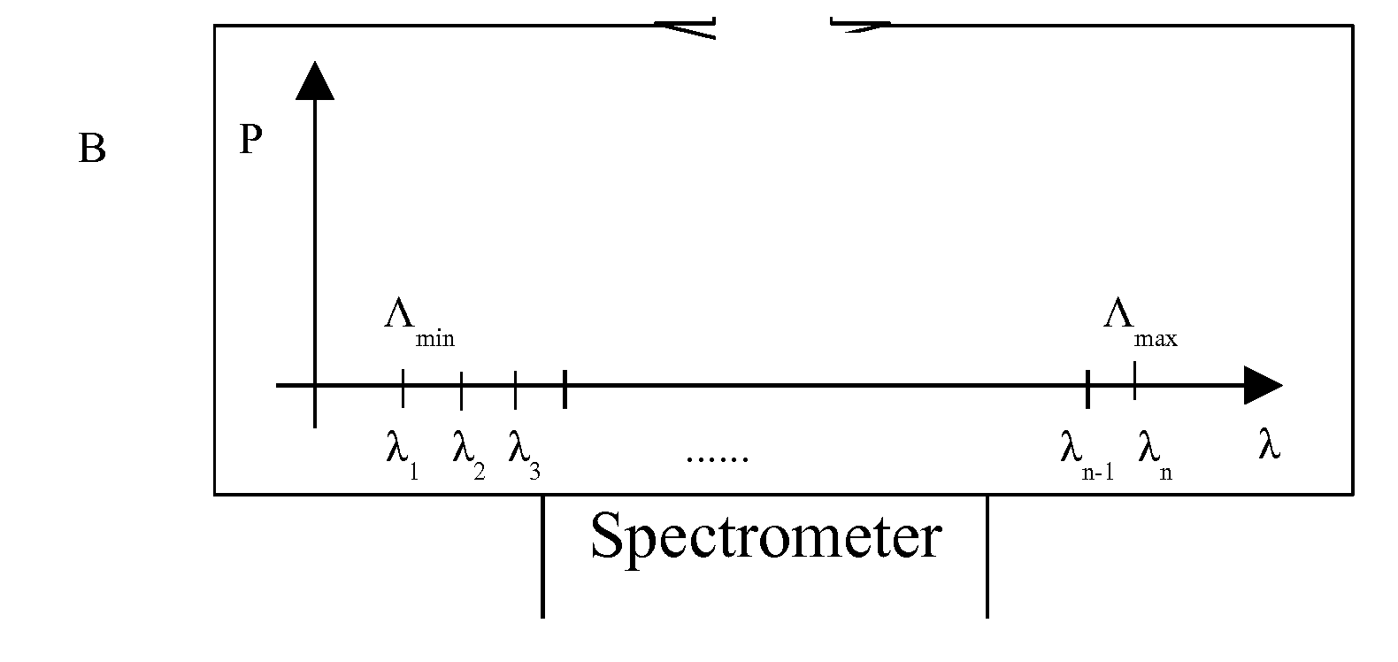
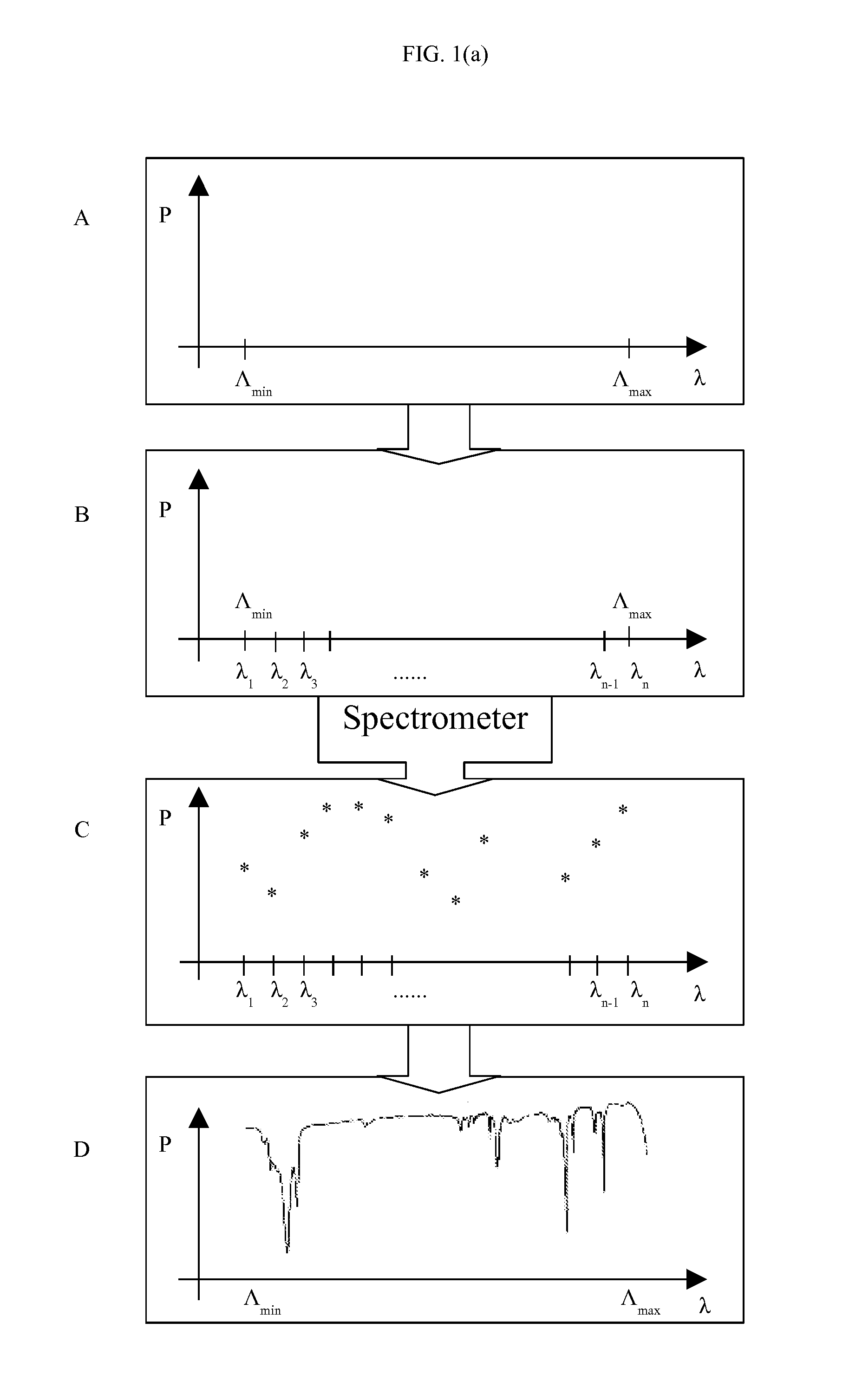
[0033]The goal of a spectrometer is to determine the function P=f(λ), where P is the power detected by a detector for wavelength λ. In the present invention, we disclose an inventive method to obtain high resolution spectroscopic data by accurately locating λ and collecting corresponding P value using a highly sensitive photon detector. The general conceptual flow chart is illustrated in FIG. 1(a), in FIG. 1(a).A, [Λmin, Λmax] is the target wavelength range to be measured, which is divided and sampled on n different wavelength values λ1, as illustrated in FIG.

[0034]1(a).B, a higher n value makes higher resolution possible. One of the inventive steps disclosed in our present invention is to achieve high n value, for example, by using high finesse tunable filter. Then said n different wavelength values λ1 are fed into the spectrometer disclosed in the present invention, a highly sensitive photo detector, for example, a photomultiplier, is utilized to collect n corresponding power valu...


PUM


Abstract

The present invention provides a spectroscopic system having a first tunable filter module, a second tunable filter module, an optical detector and a signal processing unit. The first tunable filter module includes a first tunable filter and corresponding control unit. The second tunable filter module includes a second tunable filter and corresponding control unit. The second tunable filter is configured in series with the first tunable filter, and the second tunable filter is selected so that the free spectral range of the second tunable filter matches the half-peak width of the first tunable filter. The optical detector is configured to receive wide wavelength bands of electromagnetic radiation transmitted through the first tunable filter and the second tunable filter and to generate one or more electrical signals indicative of electromagnetic radiation intensity as a function of wavelength.

Description

THE TECHNICAL FIELD[0001]The present invention relates to the art of spectrometry, spectroscopic instruments. Specifically, the present invention relates to a novel approach utilizing tunable filter to increase spectrometer resolution by as much as F times, where F is the finesse of tunable filter. The focus of the invention is in utilization of the above method to significantly increase spectral resolution of a wide range spectrometer. The invention enables creation of a simple, reliable, rugged, inexpensive and portable system for high resolution spectroscopy applications.BACKGROUND[0002]The present invention relates to a spectroscopic system having a significantly improved resolution. It is primarily concerned with the desire to combine features of high resolution, no mechanical moving parts, compact design and easy industrial deployment.[0003]Most spectrometers are based on one of the following three technologies: interferometer based Fourier Transform technology, dispersion bas...

Claims


Application Information

Patent Timeline
Patent Type & Authority Applications(United States)
IPC IPC(8): G01J3/28
CPCG01J3/28G01J3/0297G01J3/26G01J3/32G01J3/027
Inventor CHEN, QIUSHUI
Owner CHEN QIUSHUI
Why Eureka
Try Eureka