Device and method for processing photoacoustic signal

Active Publication Date: 2014-09-11
FUJIFILM CORP
View PDF5 Cites 8 Cited by
  • Summary
  • Abstract
  • Description
  • Claims
  • Application Information

AI Technical Summary

Benefits of technology

[0026]The correcting means may correct the signal from which the light differential waveform is deconvolved such that, in place of or in addition to the reception angle-dependent properties of the detector, influence of an incoming light distributi

Problems solved by technology

However, if a pressure distribution at t≠0 is reconstructed (that is, a pressure distribution at the moment when light entered (t=0) cannot be reconstructed and a pressure distribution after a while from the clock time t=0 is estimated), light pulse duration components cannot be removed and only a pressure distribution is obtained.
Therefore, although there is no problem clearly appearing in Non-Patent Documents 1 and 2, when a practical device configuration is assumed, it is difficult to reconstruct the pressure distribution at t=0 by the methods of Non-Patent Documents 1 and 2.
Further, with a sample such as an experimental living body, it is

Method used


Image

  • Device and method for processing photoacoustic signal
  • Device and method for processing photoacoustic signal
  • Device and method for processing photoacoustic signal

Examples


Embodiment Construction

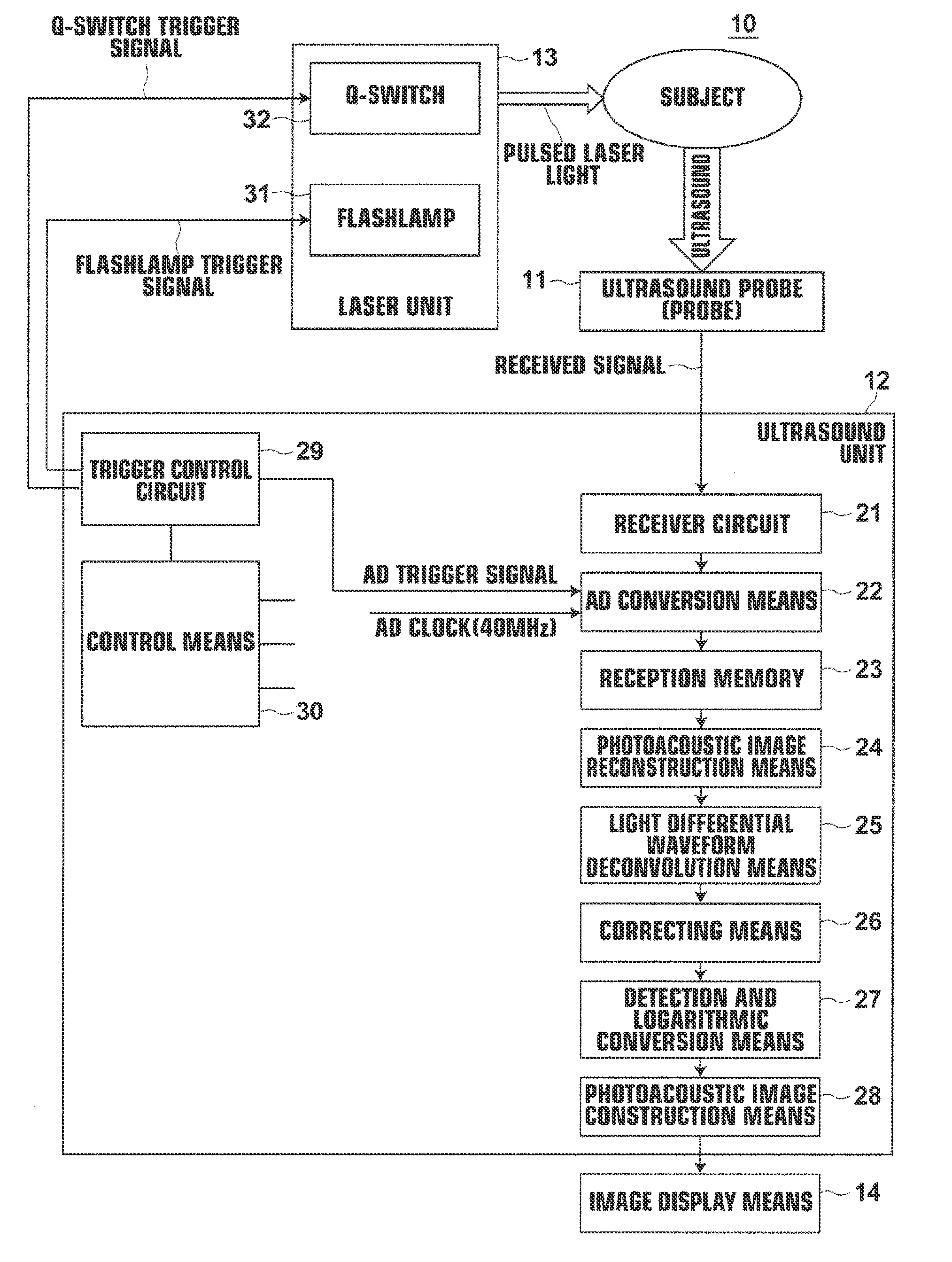
[0059]Prior to describing embodiments of the present invention, the outline of the invention is described. It is assumed here that micro absorptive particles, which are light-absorbing substances, absorb pulsed laser light and a pressure wave (photoacoustic pressure wave) is generated. According to [I. G. Calasso et al., “Photoacoustic Point Source”, PHYSICAL REVIEW LETTERS, Vol. 86, No. 16, pp. 3550-3553, 2001], a pressure waveform pmicro(R,t), which is a photoacoustic pressure wave generated by a micro absorptive particle at a position r and observed at a position R at a clock time t, is a spherical wave of the equation below:

pmicro(R,t)=kr-R(t-r-Rvs)I(t-r-Rvs),

where I(t) is a temporal waveform of light intensity of the excitation light, the coefficient k is a conversion factor when the particle absorbs light and outputs the acoustic wave, and vs is a speed of sound in the subject. Each of the positions r and R is a vector representing a spatial position. As shown by the equation ...


PUM


Abstract

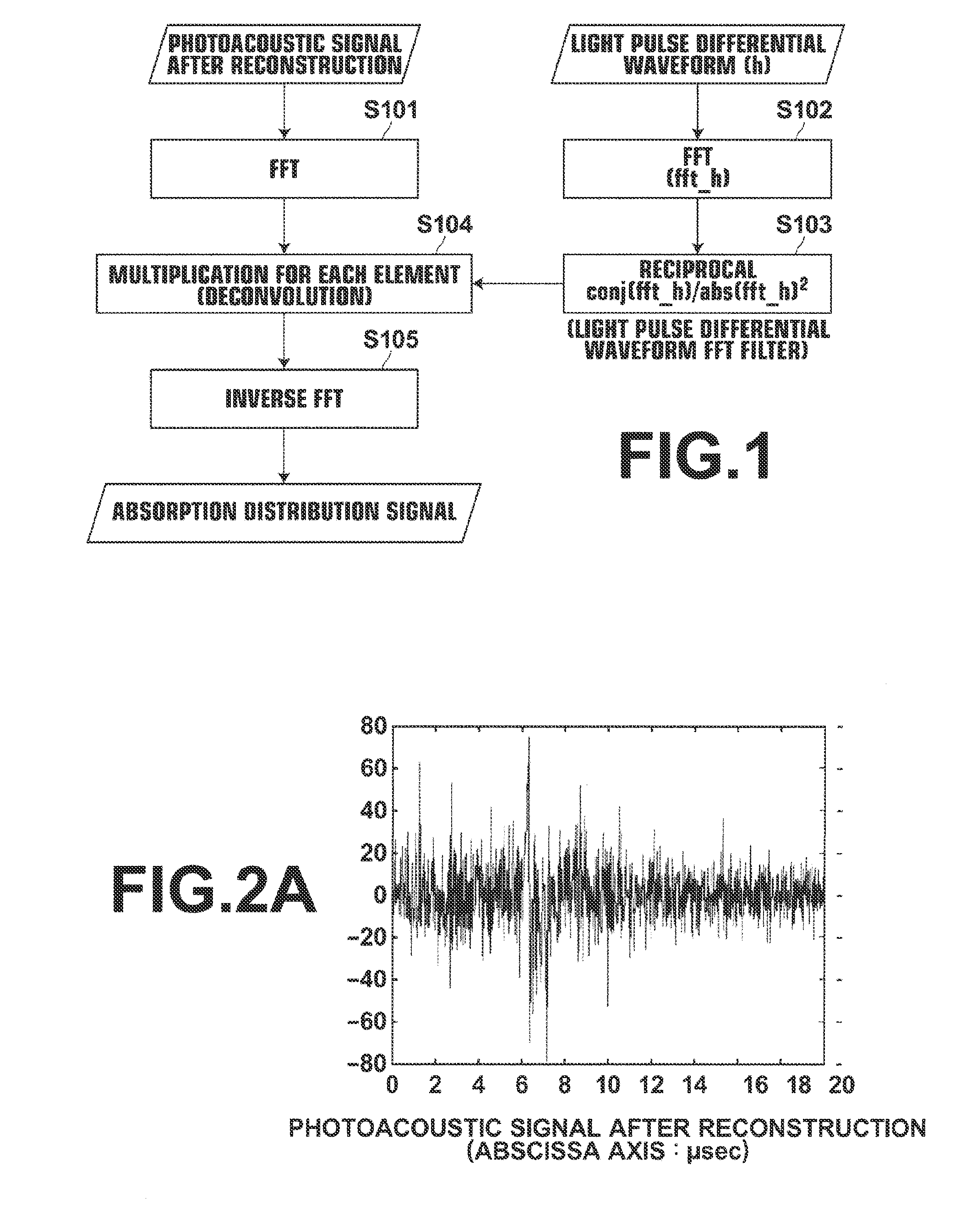
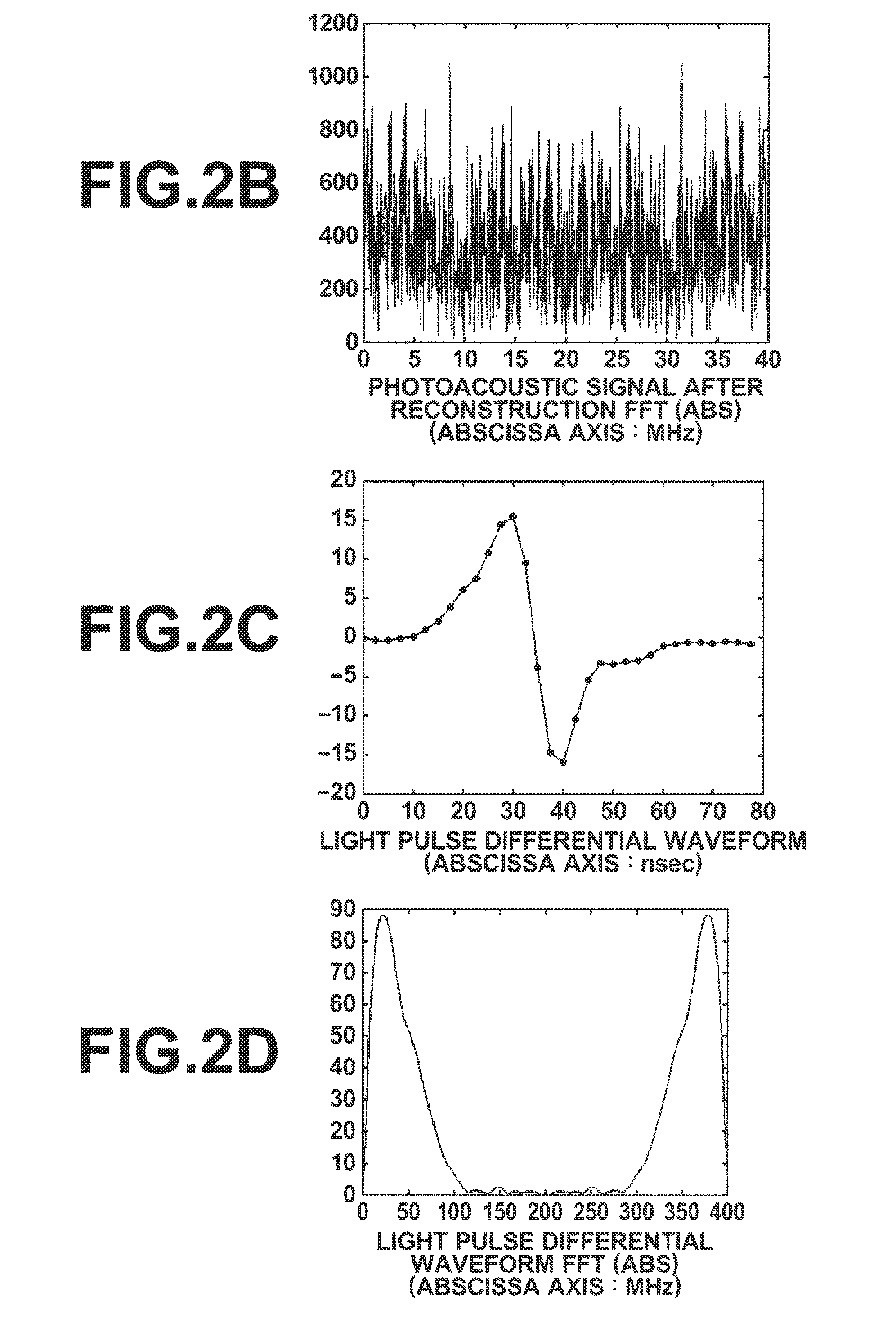
To obtain an absorption distribution from a detected signal with a practical device. Light is applied to a subject, and a photoacoustic signal generated in the subjectA photoacoustic is detected. From the detected photoacoustic signal, a light differential waveform, which is a differential waveform of a temporal waveform of the light applied to the subject, is deconvolved. As a result of this deconvolution, an absorption distribution is obtained.

Description

CROSS-REFERENCE TO RELATED APPLICATIONS[0001]This application is a Continuation of PCT International Application No. PCT / JP2012 / 007492 filed on Nov. 21, 2012, which claims priority under 35 U.S.C §119(a) to Japanese Patent Application No. 2011-254654 filed on Nov. 22, 2011 and Japanese Patent Application No. 2012-247099 filed on Nov. 9, 2012. Each of the above applications is hereby expressly incorporated by reference, in its entirety, into the present application.TECHNICAL FIELD[0002]The present invention relates to a device and a method for processing photoacoustic signals, and more particularly to a device and a method for processing photoacoustic signals that are generated in a subject due to light applied to the subject.BACKGROUND ART[0003]Ultrasonography is known as one of imaging examination methods that allow non-invasive examination of the state of the interior of a living body. In ultrasonography, an ultrasound probe that can transmit and receive ultrasound is used. Ultras...

Claims


Application Information

Patent Timeline
IPC IPC(8): A61B5/00
CPCA61B5/0095A61B5/725A61B5/7257G01N29/0654G01N29/2418G01N29/46G01N2291/02475A61B8/4416A61B5/7278A61B5/0093
Inventor IRISAWA, KAKUHIROTA, KAZUHIRO
Owner FUJIFILM CORP
Why Eureka
Try Eureka