Systems and apparatus relating to downstream fuel and air injection in gas turbines

Active Publication Date: 2014-09-18
GENERAL ELECTRIC CO
View PDF4 Cites 45 Cited by
  • Summary
  • Abstract
  • Description
  • Claims
  • Application Information

AI Technical Summary

Benefits of technology

[0005]The present application thus describes a gas turbine engine that includes: a combustor coupled to a turbine that together define an interior flowpath, the interior flowpath extending rearward about a longitudinal axis from a primary air and fuel injection system positioned at a forward end of the combustor, through an interface at which the combustor connects to the turbine, and through at least a row of stator blades in the turbine; and a downstream injection system that includes two injection stages, a first stage and a second stage, positioned within the interior flowpath, wherein the first stage and the seco

Problems solved by technology

During this time frame, however, new standards were enacted that limit the levels at which certain pollutants may be emitted during engine operation.
Of those, the emission level of NOx is especially sensitive to increased emission levels at higher engine firing temperatures and, thus,

Method used


Image

  • Systems and apparatus relating to downstream fuel and air injection in gas turbines
  • Systems and apparatus relating to downstream fuel and air injection in gas turbines
  • Systems and apparatus relating to downstream fuel and air injection in gas turbines

Examples


Embodiment Construction

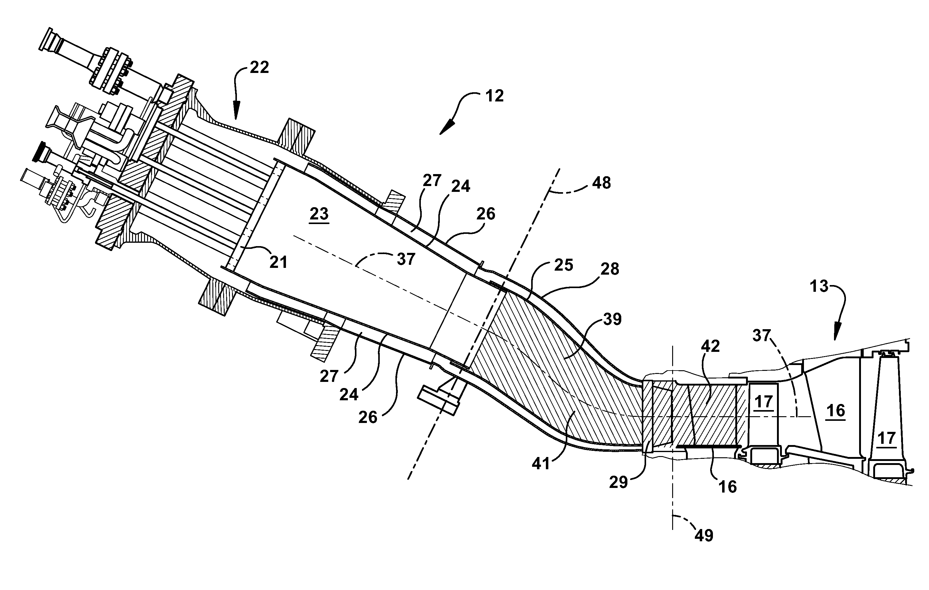
[0027]While the following examples of the present invention may be described in reference to particular types of turbine engine, those of ordinary skill in the art will appreciate that the present invention may not be limited to such use and applicable to other types of turbine engines, unless specifically limited therefrom. Further, it will be appreciated that in describing the present invention, certain terminology may be used to refer to certain machine components within the gas turbine engine. Whenever possible, common industry terminology will be used and employed in a manner consistent with its accepted meaning. However, such terminology should not be narrowly construed, as those of ordinary skill in the art will appreciate that often a particular machine component may be referred to using differing terminology. Additionally, what may be described herein as being single component may be referenced in another context as consisting of multiple components, or, what may be describ...


PUM


Abstract

A gas turbine engine that includes: a combustor coupled to a turbine and a downstream injection system that includes two injection stages, a first stage and a second stage, positioned within an interior flowpath, wherein the first stage comprises an axial position that is aft of the primary air and fuel injection system and the second stage comprising an axial position that is aft of the first stage. Each of the first stage and the second stage include a plurality of circumferentially spaced injectors, each injector of which is configured to inject air and fuel into a flow through the interior flowpath. The first stage and the second stage have a configuration that limits a fuel injected at the second stage to less than 50% of a fuel injected at the first stage.

Description

BACKGROUND OF THE INVENTION[0001]This present application relates generally to the combustion systems in combustion or gas turbine engines (hereinafter “gas turbines”). More specifically, but not by way of limitation, the present application describes novel methods, systems, and apparatus related to the downstream or late injection of air and fuel in the combustion systems of gas turbines.[0002]The efficiency of gas turbines has improved significantly over the past several decades as new technologies enable increases to engine size and higher operating temperatures. One technical basis that allowed higher operating temperatures was the introduction of new and innovative heat transfer technology for cooling components within the hot gas path. Additionally, new materials have enabled higher temperature capabilities within the combustor.[0003]During this time frame, however, new standards were enacted that limit the levels at which certain pollutants may be emitted during engine operat...

Claims


Application Information

Patent Timeline
IPC IPC(8): F23R3/28
CPCF23R3/28F23R3/20F23R3/286F23R3/346
Inventor DAVIS, JR., LEWIS BERKLEYVENKATARAMAN, KRISHNA KUMARGRAHAM, KAITLIN MARIE
Owner GENERAL ELECTRIC CO
Why Eureka
Try Eureka