Vacuum isolation valve

Active Publication Date: 2014-09-18
MST ENG
View PDF7 Cites 0 Cited by
  • Summary
  • Abstract
  • Description
  • Claims
  • Application Information

AI Technical Summary

Benefits of technology

[0010]An object of the present invention is to provide a vacuum isolation valve for facilitating isolation of a chamber

Problems solved by technology

However, the cleaning gas ionization module is vulnerable to abrasion and breakdown by nitrogen (N) and fluoride (F) ions of the nitrogen trifluoride in the course of ionization of the nitrogen trifluoride.
The resulting process delay significantly red

Method used


Image

  • Vacuum isolation valve
  • Vacuum isolation valve
  • Vacuum isolation valve

Examples


Example

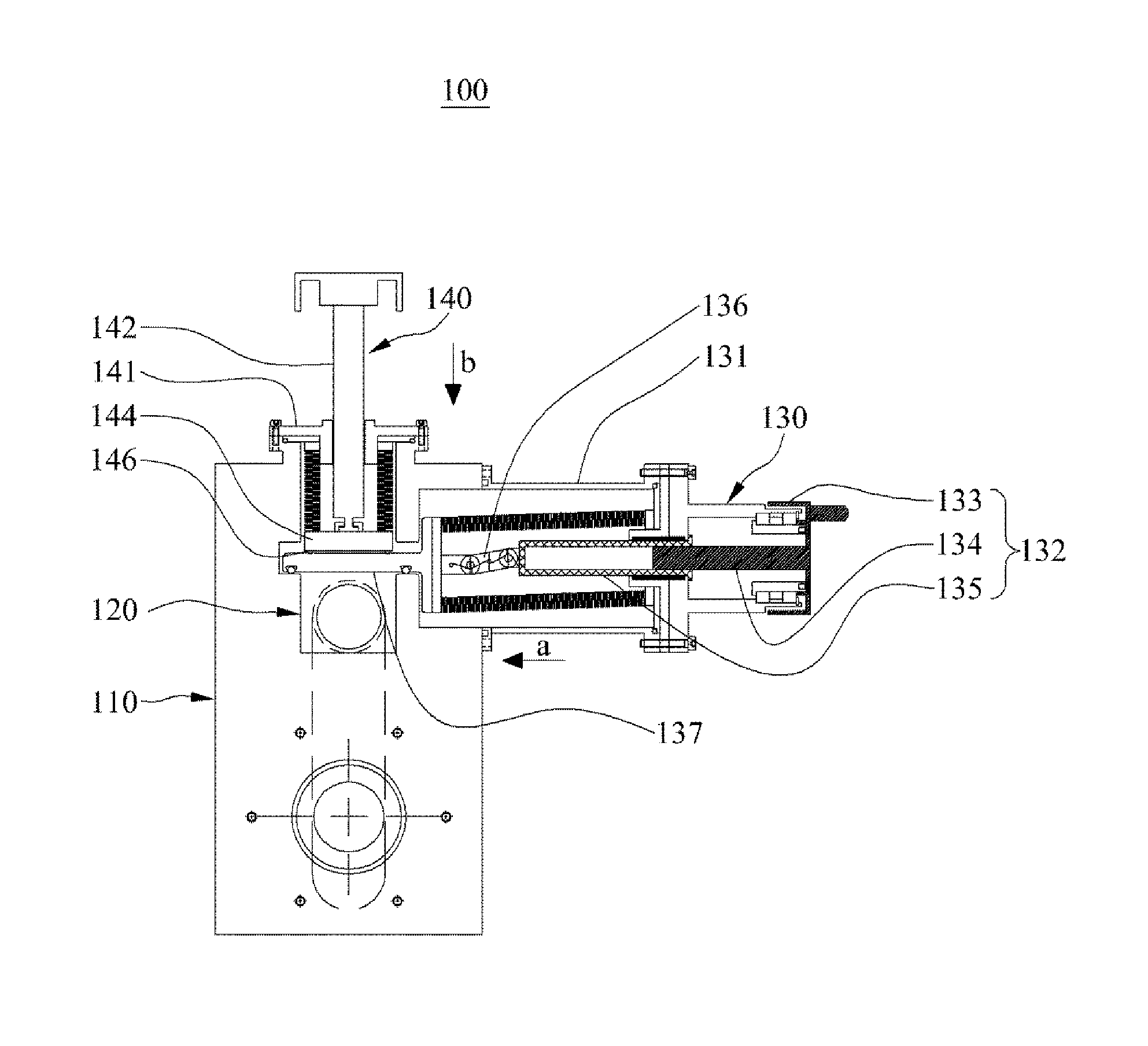
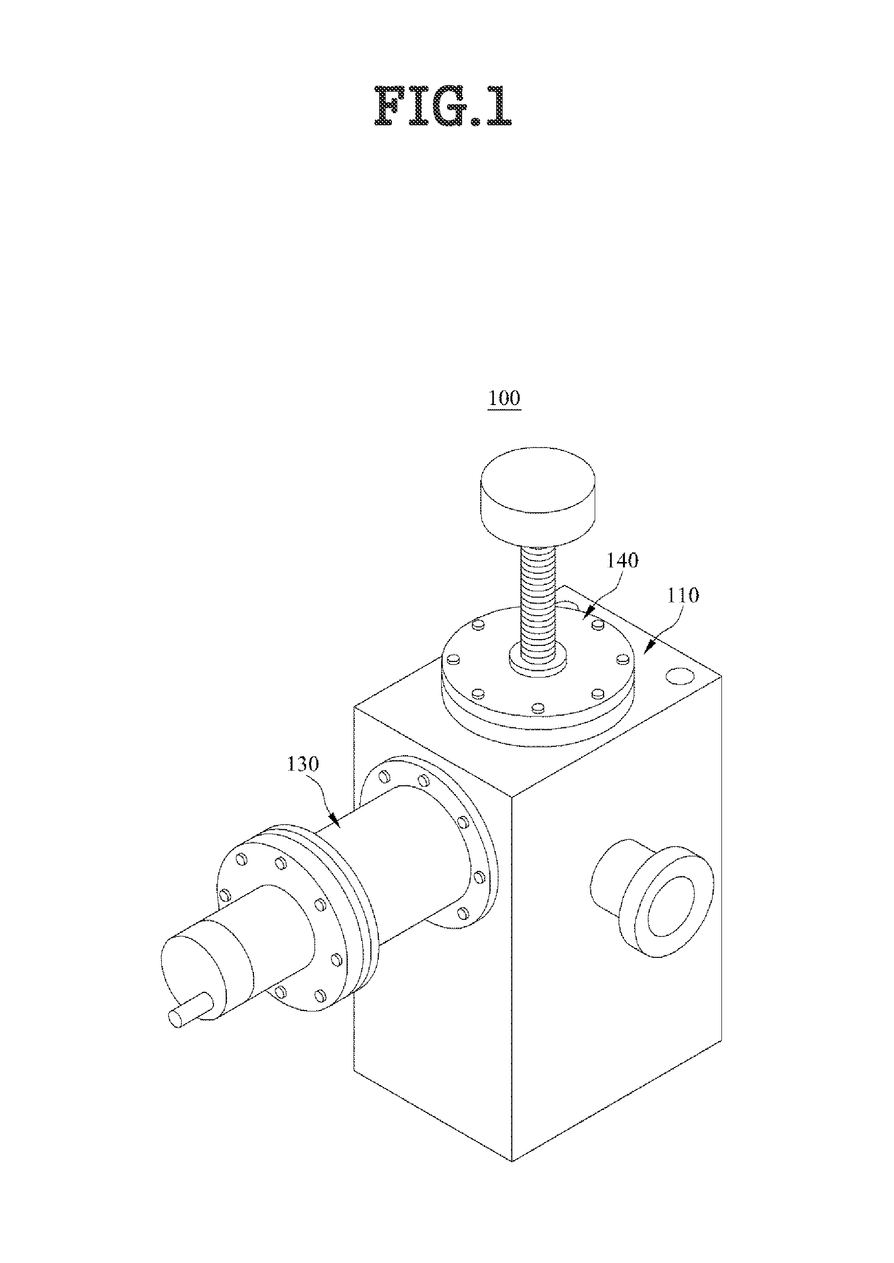
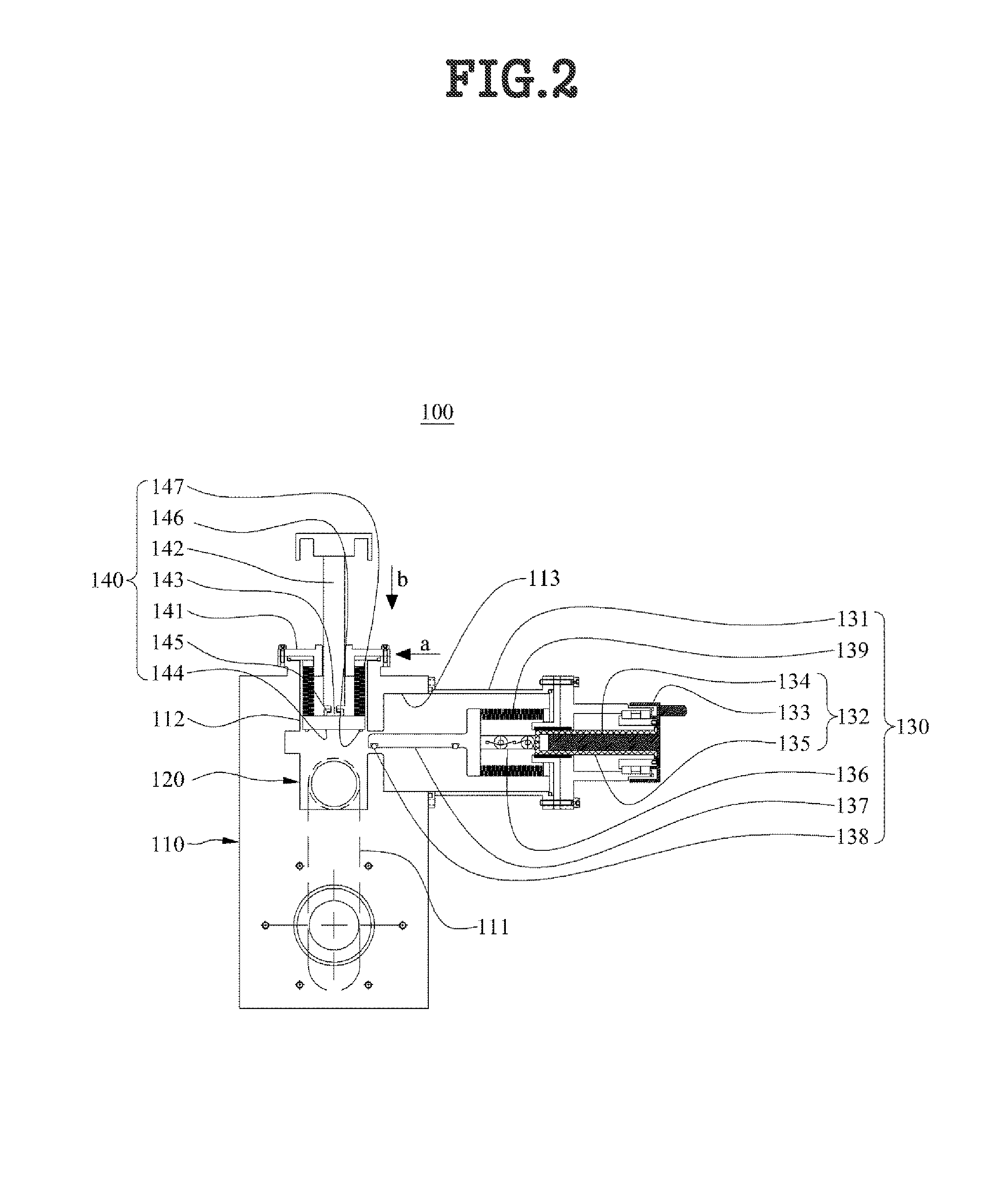
[0040]The objectives and effects of the present invention and the technical configurations of the present invention to achieve them will be apparent with reference to embodiments of the present invention described in detail with the attached drawings. A detailed description of a generally known function and structure of the present invention will be avoided lest it should obscure the subject matter of the present invention. Although the terms used in the present invention are selected from generally known and used terms, taking into account the structures, roles, and functions of the present invention, they are subject to change depending on the intention of a user or an operator or practices.

[0041]It is to be clearly understood that the present invention may be implemented in various manners, not limited to embodiments as set forth herein. The embodiments of the present invention are provided only to render the disclosure of the present invention comprehensive and indicate the scop...


PUM


Abstract

The vacuum isolation valve includes a housing installed between a chamber and a chamber cleaning gas supply and including a tube connecting the chamber to the chamber cleaning gas supply, a tube isolator formed at a predetermined position of the tube, a first blocking unit installed to the housing, and a second blocking unit installed to the housing, for, when the first blocking unit moves in the first direction, maintaining communication between the chamber and the chamber cleaning gas supply by moving in a second direction and pressing the first blocking unit and for, when the first blocking unit moves in an opposite direction to the first direction, blocking communication between the chamber and the chamber cleaning gas supply.

Description

[0001]This application claims the benefit of Korean Patent Application No. 10-2013-0026770, filed on Mar. 13, 2013, which is hereby incorporated by reference as if fully set forth herein.BACKGROUND OF THE INVENTION[0002]1. Field of the Invention[0003]The present invention relates to a vacuum isolation valve, and more particularly, to a vacuum isolation valve for effectively maintaining the inside of a chamber in a vacuum state by selectively isolating a tube that transfers a chamber cleaning gas and minimizing abrasion of a sealing member installed at a blocking part that blocks the tube.[0004]2. Discussion of the Related Art[0005]In general, a process requiring high precision such as a semiconductor or Liquid Crystal Display (LCD) fabrication process takes place in a space isolated from the outside and maintained at a constant temperature, such as a chamber. When the process is completed inside the chamber, foreign materials remain due to a processing gas in the chamber. Thus a cha...

Claims


Application Information

Patent Timeline
IPC IPC(8): B08B5/00
CPCB08B5/00F16K51/02F16K3/18H01J37/18H01J37/32862H01J2237/006H01J2237/022H01L21/67017Y10T137/4245H01L21/02
Inventor CHO, HANJUNGKIM, SANGHO
Owner MST ENG
Why Eureka
Try Eureka