
Hydrogen on demand electrolysis fuel cell system

Inactive Publication Date: 2014-09-18
NRG LOGISTICS
View PDF4 Cites 13 Cited by
  • Summary
  • Abstract
  • Description
  • Claims
  • Application Information

AI Technical Summary

Benefits of technology

The patent text describes the need for components and methods to create a novel HOD system for use in internal combustion engines. This system can improve fuel economy, reduce emissions, and increase power delivery to the vehicle's drive train. Additionally, the patent also mentions the need for a method to filter the production of HHO from an on-board fuel cell system to prevent fluid from entering the engine's air supply.

Problems solved by technology

Power production engineers have for many years sought mechanisms to harness the energy potential of hydrogen, but thus far those efforts have barely scraped the surface of that potential.
One significant detriment that is prevalent in many or most prior art systems is that the energy and resources required to produce a sufficient quantity of hydrogen with those systems typically outstrips the energy that is then recoverable from the hydrogen that is so produced.
As noted, this process is energy-intensive and inefficient to the extent that more energy may be required to produce hydrogen gas than may ultimately be recovered from that gas.
However, it is altogether impractical to implement this manner of a storage system due to the weight and bulk of the gas storage system that would be required.
Most if not all of those attempts, however, have proved to be inadequate, inefficient, or unsafe.
Some of the problems experienced with those systems include, for example, production of inadequate amounts of HHO gas; corrosion and rapid decay of the electrolyzers; and potential safety problems due to buildup of excess HHO without safety or shut-down controls, presenting an environment in which explosive combustion occurs away from the internal combustion engine.

Method used


Image

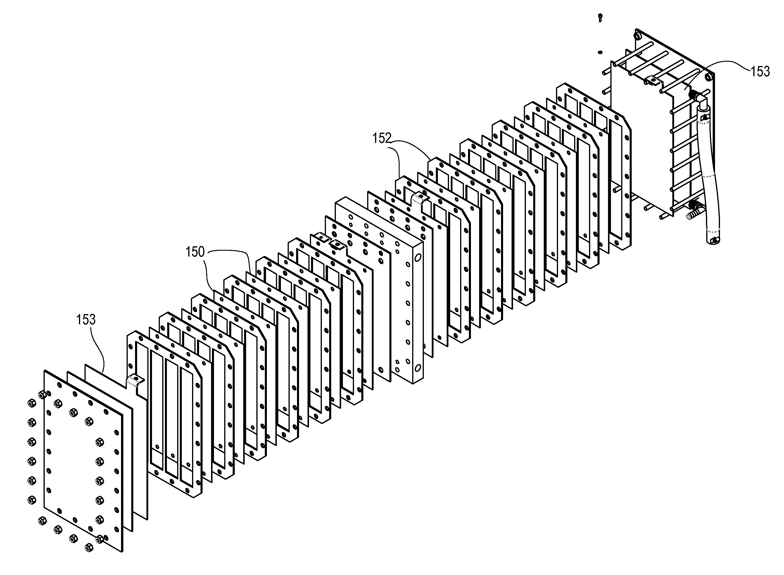
  • Hydrogen on demand electrolysis fuel cell system
  • Hydrogen on demand electrolysis fuel cell system
  • Hydrogen on demand electrolysis fuel cell system

Examples


Embodiment Construction

Schematic

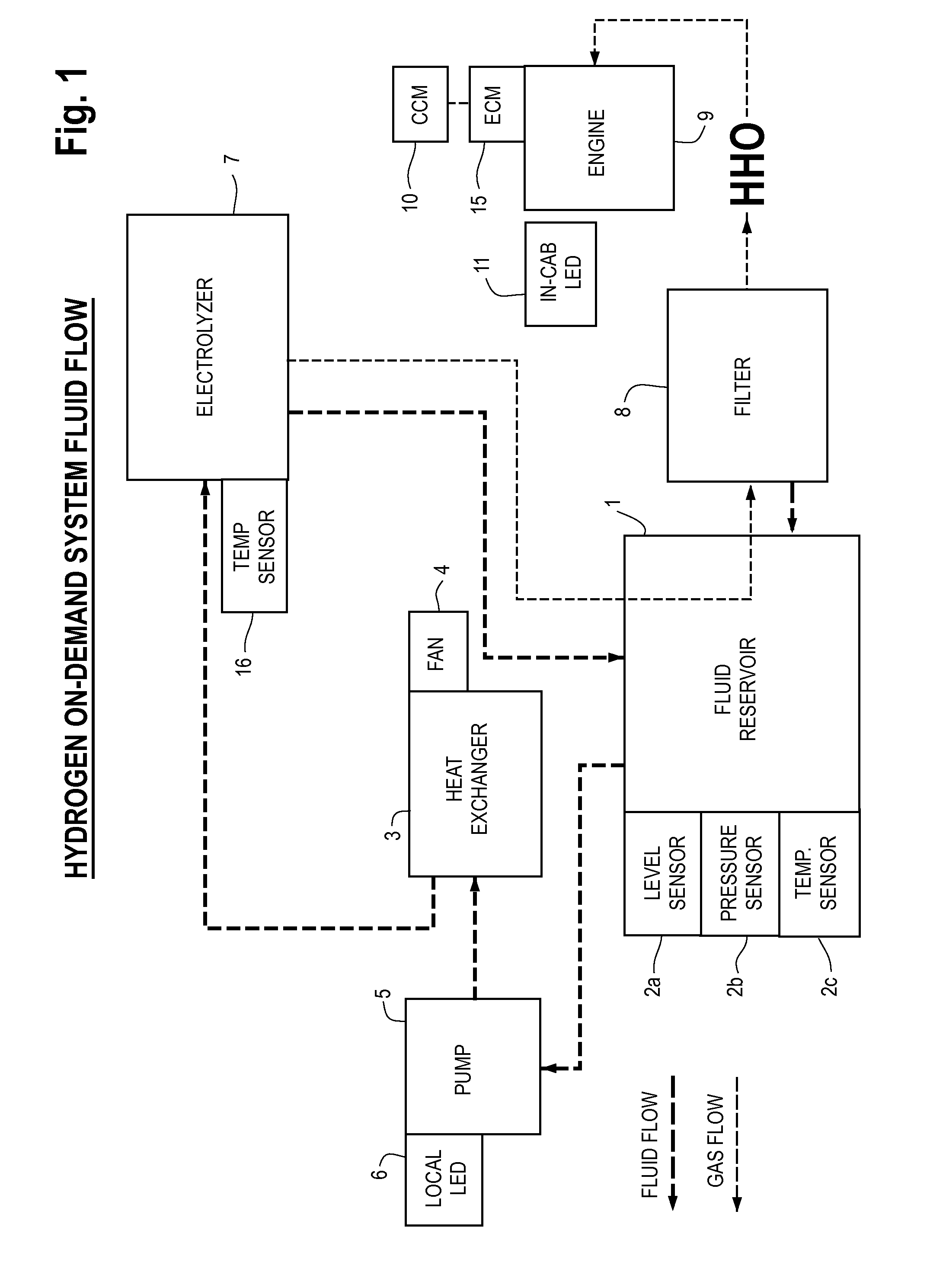
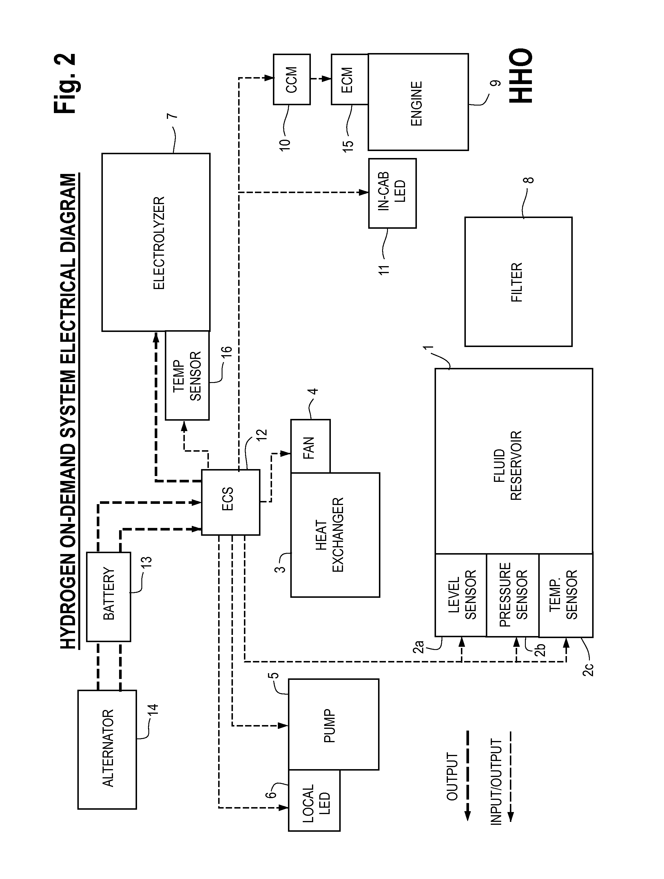
[0016]A schematic flow chart showing the components of an embodiment of an HOD system is depicted in FIG. 1. As shown therein, this system includes a fluid tank or reservoir 1 that includes at least integrated sensors 2a, 2b, and 2c to detect, for example, fluid level and both the gaseous pressure and temperature of the fluid within the reservoir. Those of skill in the art will recognize that additional or different sensors may be included. A pump 5 controls the flow of fluid from the reservoir to a heat exchanger 3 and into an electrolyzer 7. The heat exchanger 3 is utilized to adjust the temperature of an electrolyte fluid that is stored in the reservoir 1 and pumped through the system into the electrolyzer 7. The heat exchanger 3 preferably also includes an integrated fan 4 that passes air over the heat exchanger to cool the electrolyte fluid and to dissipate any excess heat generated within the heat exchanger. Light-emitting diodes (LED's) 6 or other visual indicators m...


PUM

PropertyMeasurementUnit
Volumeaaaaaaaaaa
Temperatureaaaaaaaaaa
Electrical resistanceaaaaaaaaaa

Abstract

A hydrogen and oxygen (HHO) gas on-demand electrolysis fuel cell system for use with internal combustion engines is disclosed. This hydrogen on-demand (HOD) system integrates with the engine control module (ECM) or other control system that regulates the operation of an internal combustion engine in order to supply HHO to the engine and improve the engine's overall fuel efficiency. This system includes an electrolyte fluid reservoir outfitted with level, pressure and temperature sensors; a pump and heat exchanger; a uniquely-configured electrolyzer; and a filter. The combined engine and HOD system is controlled and regulated by an electronic control system (ECS) and a combustion control module (CCM). The CCM is installed on the engine such that it actively intercepts the electronic signals from the engine manufacturer's ECM to continuously coordinate the functions and operations of the HOD system and the engine.

Description

FIELD OF THE INVENTION[0001]This specification generally describes an electrolysis fuel cell system that is designed to produce hydrogen and oxygen (HHO) gas on-demand and to supply these gasses into the combustion chambers of internal combustion engines. More specifically, this specification describes a new configuration of a hydrogen on-demand (HOD) system that integrates with the engine control module (ECM) or other control system that regulates the operation of an internal combustion engine in order to supply HHO to the engine and improve the engine's overall fuel efficiency. This system is further designed to produce a continuous flow of HHO produced via electrolysis from an aqueous fluid, which is then mixed with the engine's air supply. This system facilitates these functions by providing an integrated system comprising an insulated electrolyte fluid reservoir outfitted with level, pressure and temperature sensors; a pump and heat exchanger; a uniquely-configured electrolyzer...

Claims


Application Information

Patent Timeline
IPC IPC(8): C25B1/08
CPCC25B1/08B01D46/0039C25B1/04F02B2043/106F02M25/12Y02T10/32C25B9/73Y02E60/36Y02T10/12B01D46/0027B01D2279/60F02B43/10
Inventor FORBES, DAVID TODDGREEN, JEREMYKRUCKENBERG, CHRIS
Owner NRG LOGISTICS
Learn More