Reactor for sewage treatment

a sewage treatment and reactor technology, applied in biological water/sewage treatment, filtration separation, separation processes, etc., can solve the problems of reducing the efficiency of sewage treatment, and wasting a large volume of water for backwashing, so as to facilitate the reduction of nitrous oxide into nitrogen, the effect of improving the denitrification efficiency of the reactor and reducing the production of nitrous oxid

Active Publication Date: 2014-09-18
CHONGQING UNIV
View PDF3 Cites 15 Cited by
  • Summary
  • Abstract
  • Description
  • Claims
  • Application Information

AI Technical Summary

Benefits of technology

[0012]The aerobic zone and the anoxic zone in the outer layer of the artificial wetland and the inner layer of the biological aerated filter are alternated. The sewage is introduced to every zone for treatment, so that a carbon source required by the nitration and denitrification is ensured, and the denitrification efficiency of the reactor is improved.
[0013]The aerobic zone of the biological aerated filter is provided with aeration pipes for ensuring a high content of dissolved oxygen in the nitration process as well as eliminating the dissolved oxygen as much as possible in the denitrification process, and thus, the activity of the nitrous oxide reductase is ensured, the reduction of the nitrous oxide into nitrogen is facilitated, and the production of the nitrous oxide is reduced. Plants in the artificial wetland are capable of absorbing carbon dioxide in the air, further lowerin

Problems solved by technology

However, after a period of operation, the interception of the pollutants in the filter layer and the growing of the biofilm easily cause the obstruction of the filter layer, so that the biological aerated filter is required to backwash, which results in waste of a large volume of the water for backwashing and a large head loss.
The

Method used


Image

  • Reactor for sewage treatment
  • Reactor for sewage treatment
  • Reactor for sewage treatment

Examples


Embodiment Construction

[0020]For further illustrating the invention, experiments detailing a reactor for sewage treatment using a combination of a biological aerated filter and an artificial wetland are described below. It should be noted that the following examples are intended to describe and not to limit the invention.

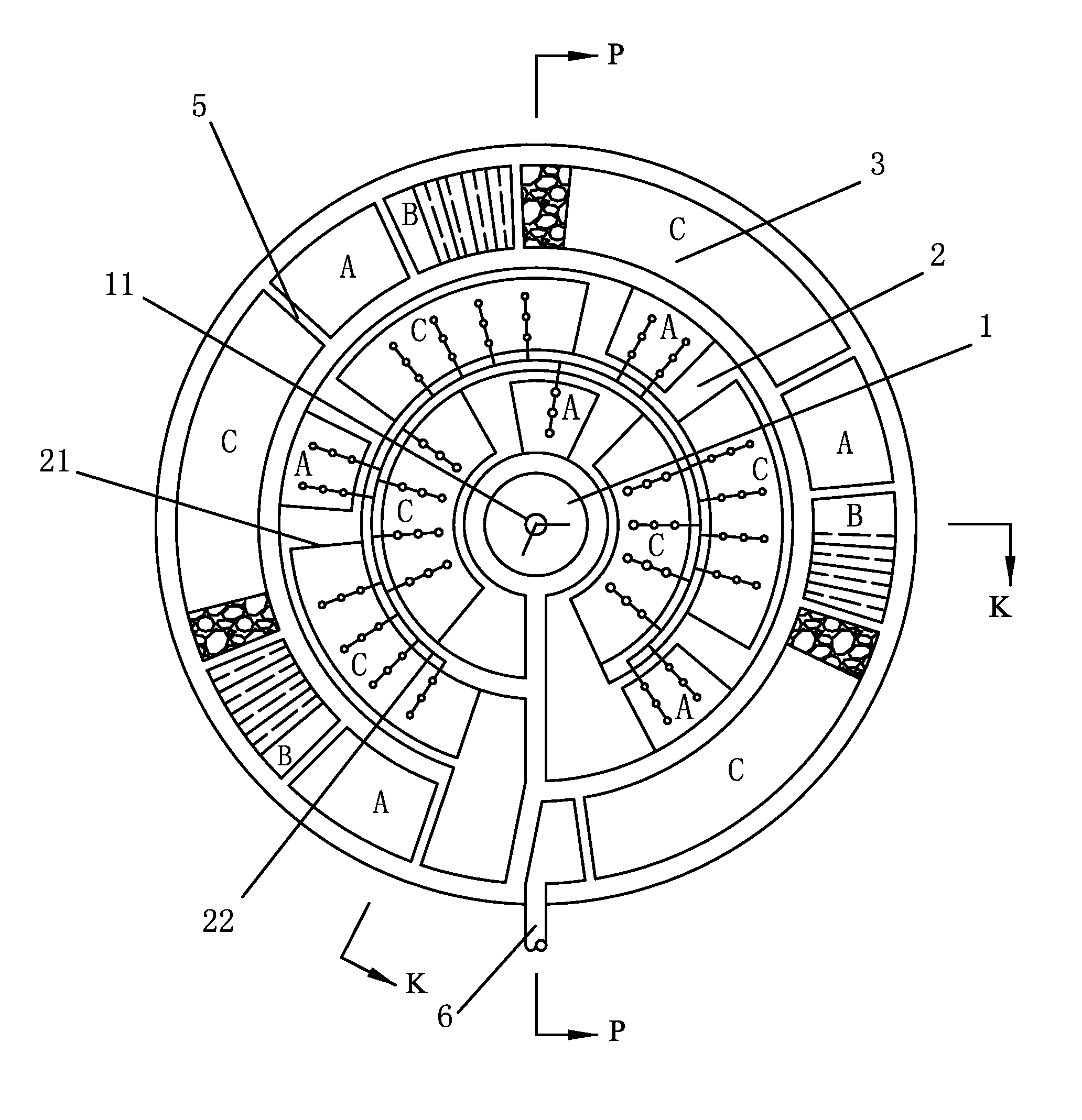
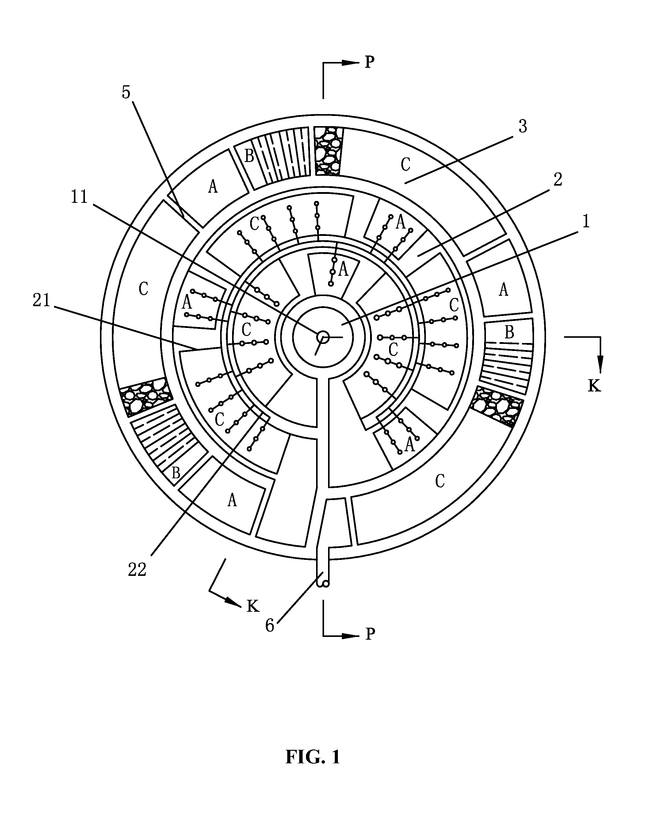
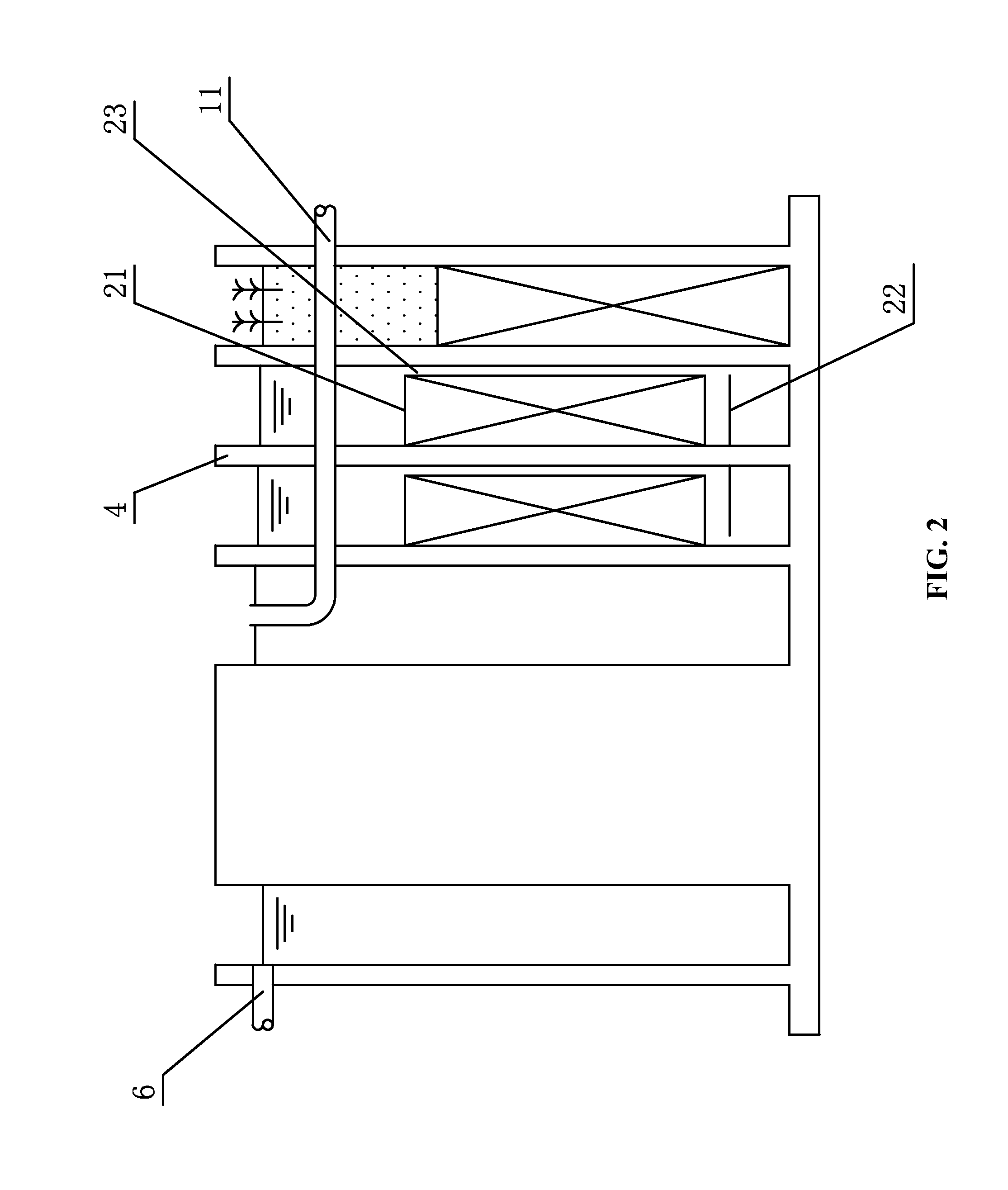
[0021]As shown in FIGS. 1-4, a reactor for sewage treatment using a combination of a biological aerated filter and an artificial wetland comprises: an inner layer comprising a water distribution zone 1; a middle layer comprising a biological aerated filter 2; and an outer layer comprising an artificial wetland 3. The water distribution zone 1, the biological aerated filter 2, and the artificial wetland 3 are in the shape of circle. Sewage is introduced into the water distribution zone 1 via a water inlet pipe 11. The water distribution zone 1 communicates with the biological aerated filter 2 via a first overflow 12. A water outlet arranged on a bottom of the biological aerated filter 2 is...


PUM

PropertyMeasurementUnit
Shapeaaaaaaaaaa
Distributionaaaaaaaaaa

Abstract

A reactor for sewage treatment including: an inner layer including a water distribution zone; a middle layer including a biological aerated filter, the biological aerated filer including a wall and a bottom including a water outlet; and an outer layer including an artificial wetland, the artificial wetland including a bottom including a water inlet. The water distribution zone, the biological aerated filter, and the artificial wetland are in the shape of a circle. The sewage is introduced into the water distribution zone via a water inlet pipe. The water distribution zone communicates with the biological aerated filter via a first overflow. The water outlet arranged on the bottom of the biological aerated filer is connected to the water inlet arranged on the bottom of the artificial wetland to allow the biological aerated filter to communicate with the artificial wetland.

Description

CROSS-REFERENCE TO RELATED APPLICATIONS[0001]Pursuant to 35 U.S.C. §119 and the Paris Convention Treaty, this application claims the benefit of Chinese Patent Application No. 201310082916.1 filed Mar. 15, 2013, the contents of which are incorporated herein by reference. Inquiries from the public to applicants or assignees concerning this document or the related applications should be directed to: Matthias Scholl P.C., Attn.: Dr. Matthias Scholl Esq., 14781 Memorial Drive, Suite 1319, Houston, Tex. 77079.BACKGROUND OF THE INVENTION[0002]1. Field of the Invention[0003]The invention relates to the field of sewage treatment and environment protection, and more particularly to a reactor for low-carbon treatment of sewage.[0004]2. Description of the Related Art[0005]Biological aerated filter (BAF) is a new technology for sewage treatment using biofilm. BAF integrates the biological oxidation and retention of suspended solid as a whole to save the space of the subsequent sedimentation tank...

Claims


Application Information

Patent Timeline
IPC IPC(8): C02F3/10
CPCC02F3/101C02F3/06C02F3/121C02F3/1247C02F3/301C02F3/302C02F3/308C02F3/327Y02A20/208Y02W10/10
Inventor CHAI, HONGXIANGKANG, WEICHEN, WEIAI, NANPINGSU, CHUANRONGWEI, ZHIWENHE, QIANGHU, XUEBINFANG, JUNHUAYAN, WENTAO
Owner CHONGQING UNIV
Why Eureka
Try Eureka