
Fluid Sanitization Assembly And Related Methods Of Use

a technology of sanitizing assembly and fluid, which is applied in the direction of instruments, other chemical processes, separation processes, etc., can solve the problems of unit/assembly not being able to properly sanitize water, the useful lifespan degradation is difficult to detect, and the fluid flow rate of the fluid is reduced. , to achieve the effect of reducing the flow rate of fluid

Inactive Publication Date: 2014-09-18
HAYWARD IND INC
View PDF12 Cites 27 Cited by
  • Summary
  • Abstract
  • Description
  • Claims
  • Application Information

AI Technical Summary

Benefits of technology

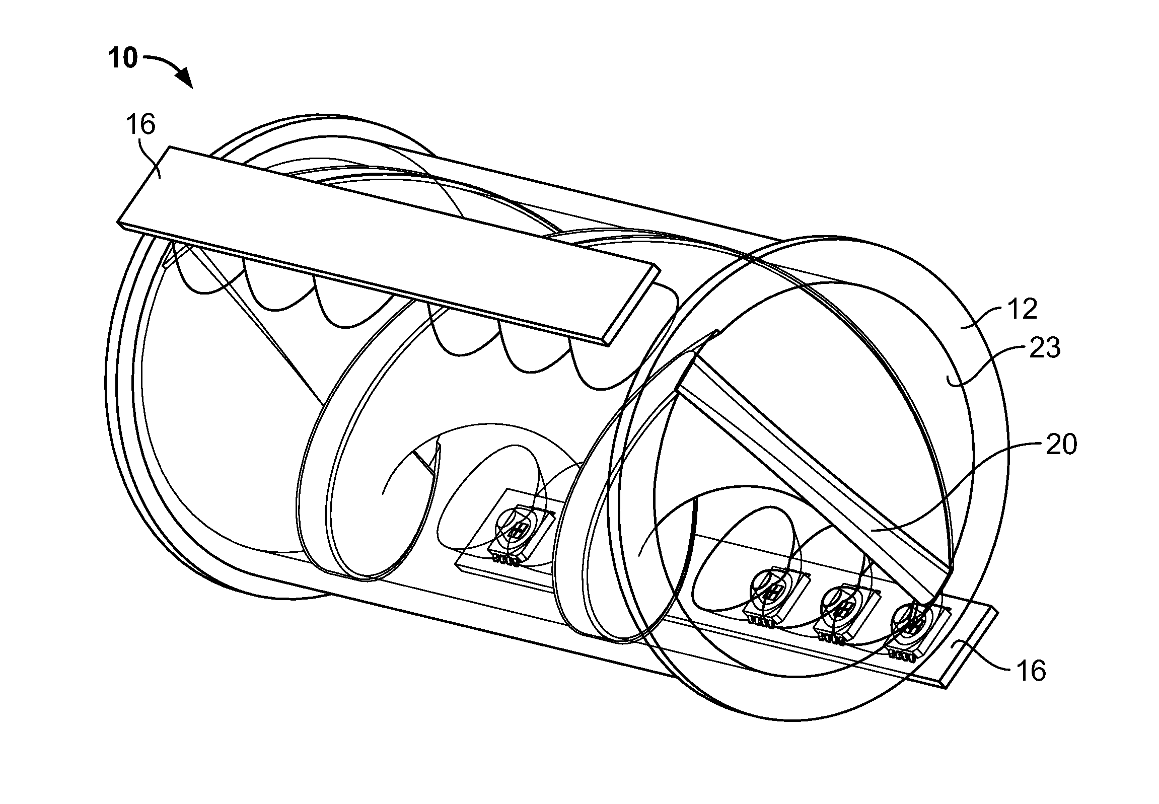
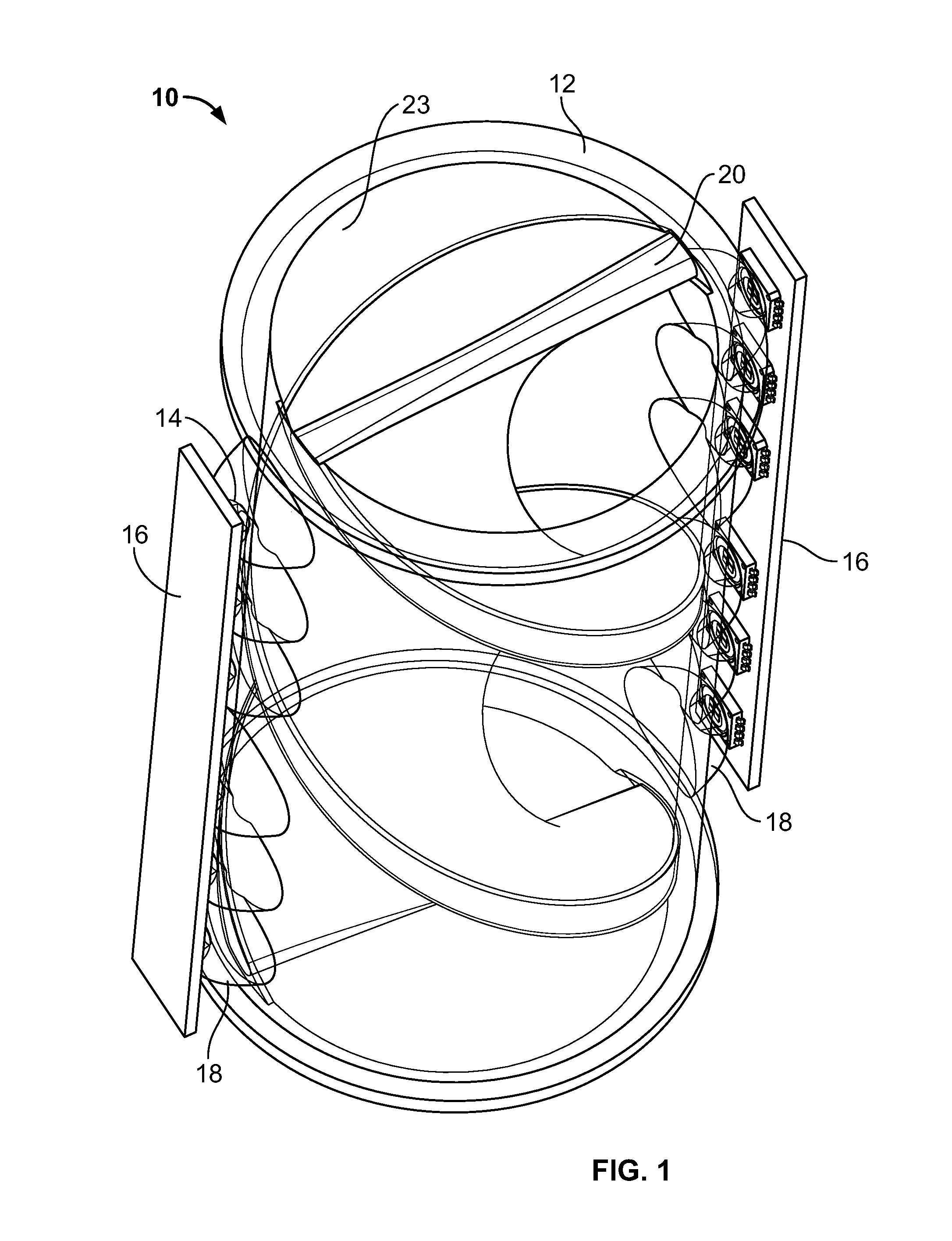
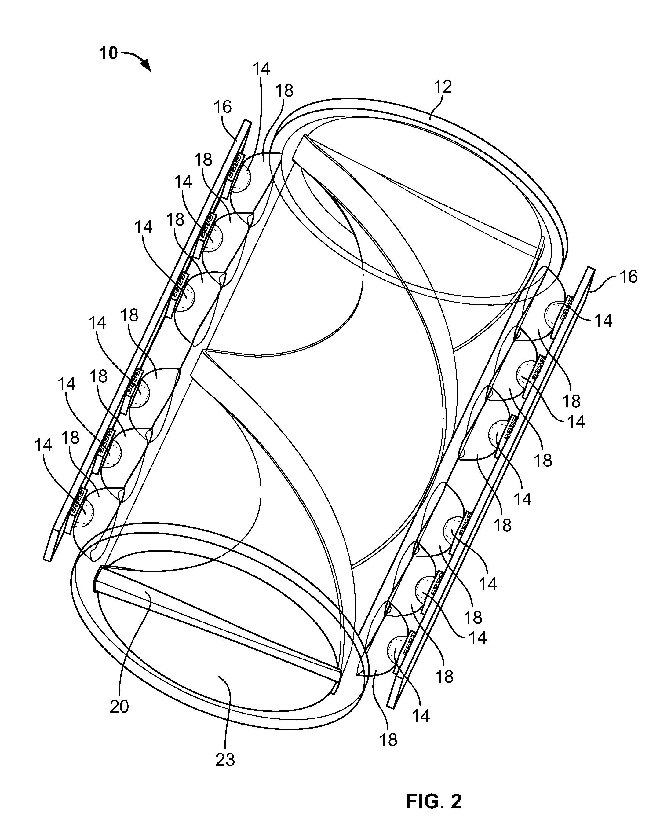
The present patent is about a fluid sanitization assembly for use in swimming pools that includes a pressure vessel with a reflective coating on its inner surface, UV LEDs mounted inside the pressure vessel with a directional optic member to focus the UV light on the fluid, a spiraled reflective insert member inside the pressure vessel that reduces the flow rate of the fluid and reflects UV light, and an ozone generator to introduce ozone to the fluid. The technical effect of this invention is a more efficient and effective method to sanitize fluid by reducing the flow rate and reflecting UV light.

Problems solved by technology

Some water sanitization assemblies utilize a conventional UV bulb design, the lifespan of which degrades after time (e.g., after several thousands of hours of use).
Such useful lifespan degradation is difficult to detect, typically other than by measuring the hours of run time.
This can create situations where the unit / assembly appears to be working because the light may be on, but the unit / assembly is no longer capable of properly sanitizing the water.
These UV lamps / bulbs also typically require a high rate of energy consumption.

Method used


Image

  • Fluid Sanitization Assembly And Related Methods Of Use
  • Fluid Sanitization Assembly And Related Methods Of Use
  • Fluid Sanitization Assembly And Related Methods Of Use

Examples


Embodiment Construction

[0035]The exemplary embodiments disclosed herein are illustrative of advantageous fluid sanitization assemblies, and systems of the present disclosure and methods / techniques thereof. It should be understood, however, that the disclosed embodiments are merely exemplary of the present disclosure, which may be embodied in various forms. Therefore, details disclosed herein with reference to exemplary fluid sanitization assemblies / fabrication methods and associated processes / techniques of assembly and / or use are not to be interpreted as limiting, but merely as the basis for teaching one skilled in the art how to make and use the advantageous fluid sanitization assemblies of the present disclosure.

[0036]The present disclosure provides improved fluid (e.g., water) sanitization assemblies. In general, the present disclosure provides improved fluid / water sanitization assemblies utilizing UV light and / or ozone. In certain embodiments, the UV light and / or ozone can be generated via light emitt...


PUM

PropertyMeasurementUnit
wavelengthaaaaaaaaaa

Abstract

Improved fluid sanitization assemblies are provided. More particularly, the present disclosure provides improved fluid / water sanitization assemblies utilizing UV light and / or ozone. The UV light and / or ozone can be generated via light emitting diodes (“LEDs”) (e.g., via UV LEDs). In certain embodiments, by emitting light at a wavelength of about 250 nm to about 270 nm (e.g., 253.7 nm), the fluid sanitization assemblies thereby disinfect and / or sanitize fluid / water. The present disclosure provides for a fluid sanitization assembly including a pressure vessel configured and dimensioned to house fluid; a plurality of light emitting diodes (“LEDs”) mounted with respect to the pressure vessel, each LED mounted with respect to the pressure vessel via an optic member; wherein each optic member is configured and dimensioned to focus and direct UV light emitted from its associated LED to the fluid within the pressure vessel for sanitization purposes.

Description

CROSS-REFERENCE TO RELATED APPLICATIONS[0001]This application claims the benefit of U.S. Provisional Application No. 61 / 792,277 filed Mar. 15, 2013, all of which is herein incorporated by reference in its entirety.BACKGROUND[0002]1. Technical Field[0003]The present disclosure relates to fluid sanitization assemblies, and more particularly, to fluid (e.g., water) sanitization assemblies utilizing ultraviolet (“UV”) light and / or ozone.[0004]2. Background Art[0005]In general, fluid sanitization assemblies are known. For example, assemblies for sanitizing and / or disinfecting water have been developed. Fluid (e.g., water) sanitization assemblies are useful in a myriad of different environments for various uses / applications, such as commercial and / or industrial applications. For example, some fluid sanitization assemblies are described and disclosed in U.S. Pat. Nos. 3,079,498; 3,336,099; 4,842,723; 6,991,735; 7,767,168 and 8,043,500, the entire contents of each being hereby incorporated ...

Claims


Application Information

Patent Timeline
Patent Type & Authority Applications(United States)
IPC IPC(8): E04H4/12E04H4/16C02F1/78C02F1/32
CPCE04H4/1209E04H4/16C02F1/78C02F1/32A61L2/10A61L2/183A61L2202/11A61L2202/122C02F1/325C02F2103/20C02F2103/42C02F2201/3222C02F2201/3227C02F2201/3228C02F2201/326C02F2201/328C02F2201/784C02F2301/02C02F2303/04C02F2305/023A61L2/00
Inventor CARTER, III, JAMES ANTHONYSAWYER, JR., DOUGLAS M.
Owner HAYWARD IND INC
Learn More