Dual magnetic phase rotor laminations for induction machines

a technology of induction machine and phase rotor, which is applied in the direction of dynamo-electric machines, magnetic circuits characterised by magnetic materials, electrical apparatus, etc., can solve the problems of reducing the efficiency of the motor, sacrificing the efficiency or power density of the motor, and similar drawbacks to the motor performance, so as to reduce the leakage inductance

Inactive Publication Date: 2014-09-18
GENERAL ELECTRIC CO
View PDF6 Cites 16 Cited by
  • Summary
  • Abstract
  • Description
  • Claims
  • Application Information

AI Technical Summary

Benefits of technology

[0015]In accordance with another aspect of the invention, a rotor assembly for an induction machine includes a rotor core having a plurality of slots formed therein that are enclosed within the rotor core by a plurality of slot closure portions of the rotor core and a plurality of rotor conductors coupled to the rotor core and positioned thereabout within the slots of the rotor core, with the plurality of rotor conductors enclosed within the rotor core by the plurality of slot enclosure portions. The rotor core comprises a plurality of integral, non-segmented rotor laminations that are stacked and joined to collectively form the rotor core, with each of the rotor laminations being composed of a dual magnetic phase material such that the slot closure portions of each rotor lamination are in a non-magnetic state and a remaining portion of each rotor lamination is in a magnetic state, with the non-magnetic slot closure portions reducing a leakage inductance of the rotor core.

Problems solved by technology

However, it is recognized that when electrical machines are used for traction applications in hybrid / electric vehicles, there is a clear tradeoff between power density, efficiency, and the machine's constant power speed range—and that this tradeoff presents numerous design challenges.
Various techniques for reducing the leakage reactance of the motor have previously been attempted; however, these techniques result in a sacrifice to the motor's efficiency or power density, or similar drawback to motor performance.
These techniques (and associated drawbacks) include: (1) decreasing the stack length of the motor, which results in a decrease in motor efficiency; (2) decreasing the slot depth of the stator slots, which increases rotor bar losses and decreases motor efficiency; (3) eliminating any skew in the rotor or stator of the motor meant to decrease torque ripple—thus increasing the output torque ripple if the skew is removed; (4) decreasing the number of turns in the stator winding to decrease the end-winding leakage reactance contribution to the overall leakage reactance, such that, with fewer turns per phase, the stack length of the motor must increase to achieve the motor's desired voltage and power level; and (5) increasing the motor's maximum voltage to improve the high-speed torque capability without affecting the leakage reactance of the motor, with the drawback that, in many applications, there is a voltage limit that cannot be exceeded due to inverter or other system requirements.
It is also recognized that open slots can be provided on the stator side to reduce slot leakage inductance and / or can be provided on the rotor side—but that this typically is not very practical, especially with the casting of the rotor cage.

Method used


Image

  • Dual magnetic phase rotor laminations for induction machines
  • Dual magnetic phase rotor laminations for induction machines
  • Dual magnetic phase rotor laminations for induction machines

Examples


Embodiment Construction

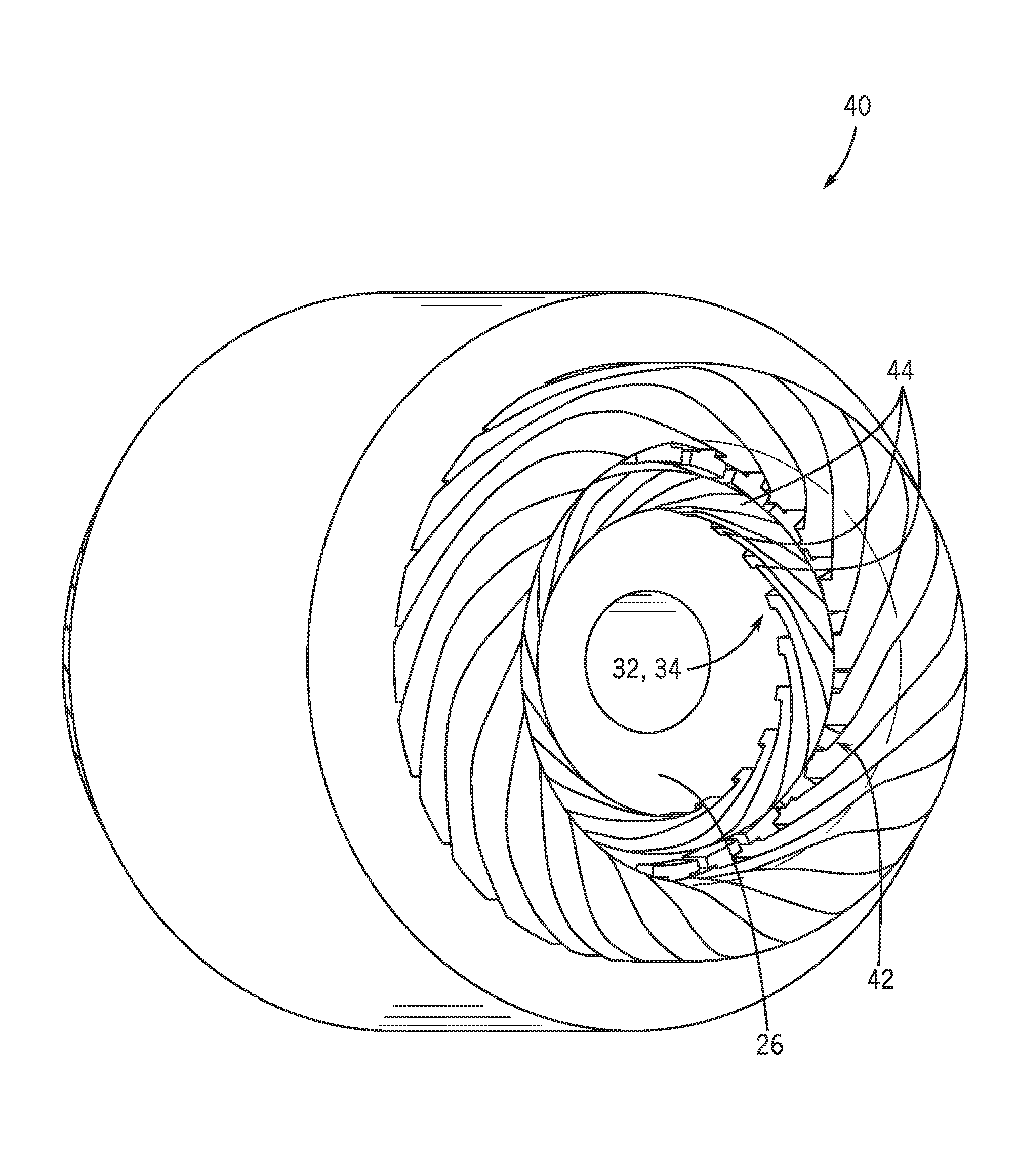
[0027]Referring to FIGS. 4-6, an AC induction machine 10 (i.e., induction motor), and respective components thereof, is illustrated according to an embodiment of the invention. Induction motor 10 includes a stator 12 and a rotor assembly 14 (i.e., “rotor”). Stator 12 further includes a stator core 16 and windings 18 wound on the stator core 16. The stator core 16 has a core main body 20 formed, for example, by stacking a large number of annular-shaped thin plates (not shown) made of electromagnetic steel and insulators (not shown) provided on axial end surfaces of the core main body. The stator core 16 is provided with a plurality of teeth 22 at a predetermined pitch along a circumferential direction thereof. According to an exemplary embodiment, windings 18 are wound on the respective teeth 22, with slots 24 formed between adjacent teeth 22 along the circumferential direction.

[0028]As shown in FIG. 4, rotor assembly 14 is constructed as a squirrel-cage type rotor that includes a ro...


PUM


Abstract

A dual magnetic phase rotor lamination for use in induction machines is disclosed. A rotor assembly is provided that includes a rotor core and a plurality of rotor conductors mechanically coupled to the rotor core and positioned thereabout, with the plurality of rotor conductors positioned within slots formed in the rotor core. The rotor core comprises a plurality of rotor laminations that collectively form the rotor core, with each of the rotor laminations being composed of a dual magnetic phase material and including a first rotor lamination portion comprising a magnetic portion and a second rotor lamination portion comprising a non-magnetic portion, wherein the second rotor lamination portion comprises a treated portion of the rotor lamination that is rendered non-magnetic so as to adjust a leakage inductance of the induction machine.

Description

CROSS-REFERENCE TO RELATED APPLICATION[0001]The present application is a non-provisional of, and claims priority to, U.S. Provisional Patent Application Ser. No. 61 / 785,020, filed Mar. 14, 2013, the disclosure of which is incorporated herein by reference.GOVERNMENT LICENSE RIGHTS[0002]This invention was made with Government support under contract number DE-EE0005573 awarded by the United States Department of Energy. The Government has certain rights in the invention.BACKGROUND OF THE INVENTION[0003]The invention relates generally to electrical machines and, more particularly, to a dual magnetic phase rotor lamination for use in induction machines.[0004]The need for high power density and high efficiency electrical machines (i.e., electric motors and generators) has long been prevalent for a variety of applications, particularly for hybrid and / or electric vehicle traction applications. The current trend in hybrid / electric vehicle traction motor applications is to increase rotational ...

Claims


Application Information

Patent Timeline
Patent Type & Authority Applications(United States)
IPC IPC(8): H02K1/02
CPCH02K1/02H02K17/165
Inventor GALIOTO, STEVEN JOSEPHEL-REFAIE, AYMAN MOHAMED FAWZI
Owner GENERAL ELECTRIC CO
Why Eureka
Try Eureka