Lighting device and projector

a technology of projector and light source, which is applied in the direction of lighting and heating apparatus, instruments, spectral modifiers, etc., can solve the problems of liquid crystal panel degradation, difficult instantaneous light emission, and relatively short life of discharge lamps of this type, and achieve the effect of reducing size and high quality

Inactive Publication Date: 2014-09-18
SEIKO EPSON CORP
View PDF13 Cites 46 Cited by
  • Summary
  • Abstract
  • Description
  • Claims
  • Application Information

AI Technical Summary

Benefits of technology

[0009]An advantage of some aspects of the invention is to provide a lighting device that is compact and lightweight and capable of efficiently outputting illumination light and a projector including the lighting device.
[0011]According to the configuration of the lighting device described above, the first reflector disposed in the optical path between the retardation film and the phosphor layer reflects part of the first light flux toward the polarization separation element and transmits the other part of the first light flux toward the phosphor layer. Further, the second reflector, which is disposed on the opposite side of the phosphor layer to the first reflector, reflects the light produced by the phosphor layer. As a result, illumination light that is a combination of light of the first wavelength band and light of the second wavelength band can be provided. A lighting device that is compact and lightweight and capable of efficiently outputting illumination light can thus be provided.
[0025]According to the configuration, the light reflective, adhesive can reflect light that leaks through the side surface of the phosphor layer back into the phosphor layer, whereby the light produced by the phosphor layer can be extracted with increased efficiency.
[0027]According to the configuration, not only can high-luminance, high-power illumination light be provided, but also the size of the light source can be reduced. Further, since the polarization direction of the first light flux coincides with one of the polarization direction of polarized light that the polarization separation element transmits and the polarization direction of polarized light that the polarization separation element reflects, the polarization separation element efficiently reflects or transmits the first light flux emitted from the semiconductor laser toward the fluorescence emitting element.
[0033]According to the configuration of the projector described above, the projector can display an image of high quality and can be further reduced in size.

Problems solved by technology

On the other hand, a discharge lamp of this type has problems of a relatively short life, a difficulty in instantaneous light emission, degradation of a liquid crystal panel due to ultraviolet light radiated from the lamp, and others.

Method used


Image

  • Lighting device and projector
  • Lighting device and projector
  • Lighting device and projector

Examples


first embodiment

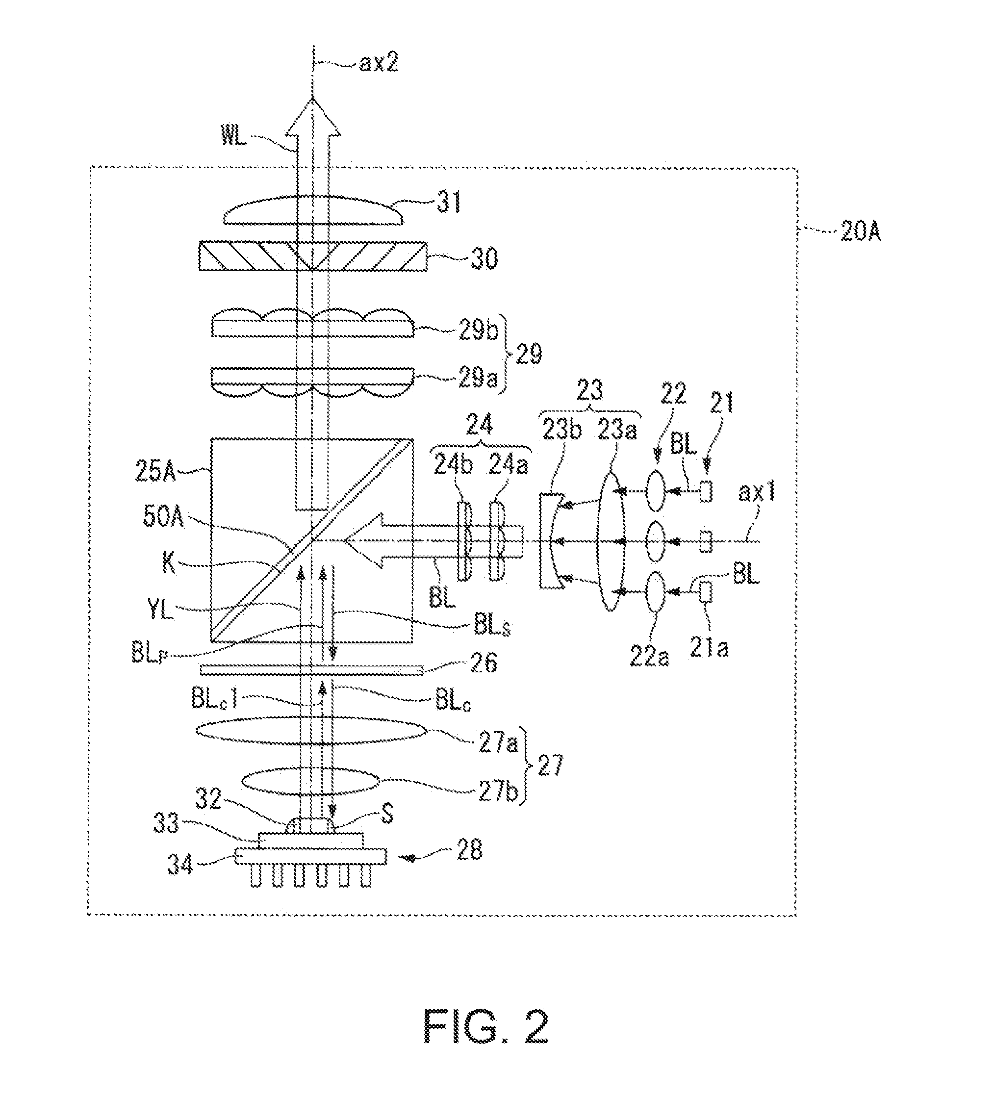
[0055]A description will first be made of a lighting device 20A shown in FIG. 2 as a first embodiment.

[0056]FIG. 2 is a plan view showing a schematic configuration of the lighting device 20A.

[0057]The lighting device 20A generally includes an array light source 21, a collimator optical system 22, an afocal optical system 23, a homogenizer optical system 24, an optical element 25A including a polarization separation element 50A, a retardation film 26, an optical pickup system 27, a fluorescence light emitting element 28, an optical integration optical system 29, a polarization conversion element 30, a superimposing optical system 31, as shown in FIG. 2.

[0058]The array light source 21 is formed of an array of a plurality of semiconductor lasers 21a. Specifically, the plurality of semiconductor lasers 21a are arranged in an array in a plane perpendicular to an optical axis. The optical axis of a first light source portion 21A is called an optical axis ax1. The optical axis of a second ...

second embodiment

[0096]A lighting device 20B shown in FIG. 4 will next be described as a second embodiment.

[0097]In the following description, the same portions as those of the lighting device 20A shown in FIG. 2 will not be described but have the same reference characters in the drawings.

[0098]In the lighting device 208B, the array light source 21, the collimator optical system 22, the afocal optical system 23, the homogenizer optical system 24, an optical element 25B including a polarization separation element 50B, the retardation film 26, the optical pickup system 27, and the fluorescence light emitting element 28 are disposed in this order along the optical axis ax1, as shown in FIG. 4. Further, the optical element 25B, the optical integration optical system 29, the polarization conversion element 30, and the superimposing optical system 31 are disposed in this order along the optical axis ax2.

[0099]The polarization separation element 50B has a polarization separation function of separating the ...


PUM


Abstract

A lighting device includes a light source that emits a first light flux of a first wavelength band, a fluorescence light emitting element including a phosphor layer which produces, when excited by light of the first wavelength band, light of a second wavelength band, a polarization separation element that has a polarization separation function for light of the first wavelength band and transmits or reflects light of the second wavelength band, a retardation film disposed in an optical path between the polarization separation element and the phosphor layer, a first reflector disposed in an optical path between the retardation film and the phosphor layer, and a second reflector that reflects the light produced by the phosphor layer. The first reflector reflects part of the first light flux toward the polarization separation element, and transmits the other part of the first light flux toward the phosphor layer.

Description

BACKGROUND[0001]1. Technical Field[0002]The present invention relates to a lighting device and a projector.[0003]2. Related Art[0004]There is a widely known projector of related art in which a light modulator is illuminated with illumination light outputted from a lighting device and modulated image light outputted from the light modulator is enlarged and projected through a projection optical system on a screen.[0005]A discharge lamp, such as an ultrahigh-pressure mercury lamp, is used as a light source of the projector in related art. On the other hand, a discharge lamp of this type has problems of a relatively short life, a difficulty in instantaneous light emission, degradation of a liquid crystal panel due to ultraviolet light radiated from the lamp, and others.[0006]In view of the fact described above, a laser light source, such as a semiconductor laser (LD) capable of emitting high-luminance, high-power light, has received attention as the light source of the projector in pla...

Claims


Application Information

Patent Timeline
Patent Type & Authority Applications(United States)
IPC IPC(8): G03B21/20F21V13/08
CPCF21V13/08G03B21/204G03B21/2073
Inventor AKIYAMA, KOICHIKUROI, KIYOSHI
Owner SEIKO EPSON CORP
Why Eureka
Try Eureka