
Laser sampling methods for reducing thermal effects

a laser and sampling method technology, applied in the direction of optical radiation measurement, instruments, spectrometry/spectrophotometry/monochromators, etc., can solve the problems of multiple laser pulse overlap, low icp-ms sensitivity and fractionation, and achieve the effect of reducing thermal effects of laser ablation

Inactive Publication Date: 2014-09-18
ELEMENTAL SCI LASERS LLC
View PDF3 Cites 49 Cited by
  • Summary
  • Abstract
  • Description
  • Claims
  • Application Information

AI Technical Summary

Benefits of technology

The patent describes a method for reducing thermal effects in laser ablation optical emission spectrometry. This is achieved by creating discrete ablation spots on a target surface along an analysis line and positioning them so that they are separated from each other by a further ablation spot. This separation results in a linear scan of isolated ablation spots, which can be used to generate accurate data. The method can also include creating multiple ablation spots and positioning them to minimize thermal effects and improve accuracy.

Problems solved by technology

This mode of sampling can cause multiple laser pulse overlap as the laser frequency (pulsed laser) is typically faster than the stage movement.
Multiple pulse overlap causes progressive heating of the sample which has been shown to be detrimental to data quality i.e. a thermal mechanism to the ablation causes melting of the sample and formation of large particles which causes low ICP-MS sensitivity and fractionation; consequently the result is not representative of the true composition of the sample.

Method used


Image

  • Laser sampling methods for reducing thermal effects
  • Laser sampling methods for reducing thermal effects
  • Laser sampling methods for reducing thermal effects

Examples


Embodiment Construction

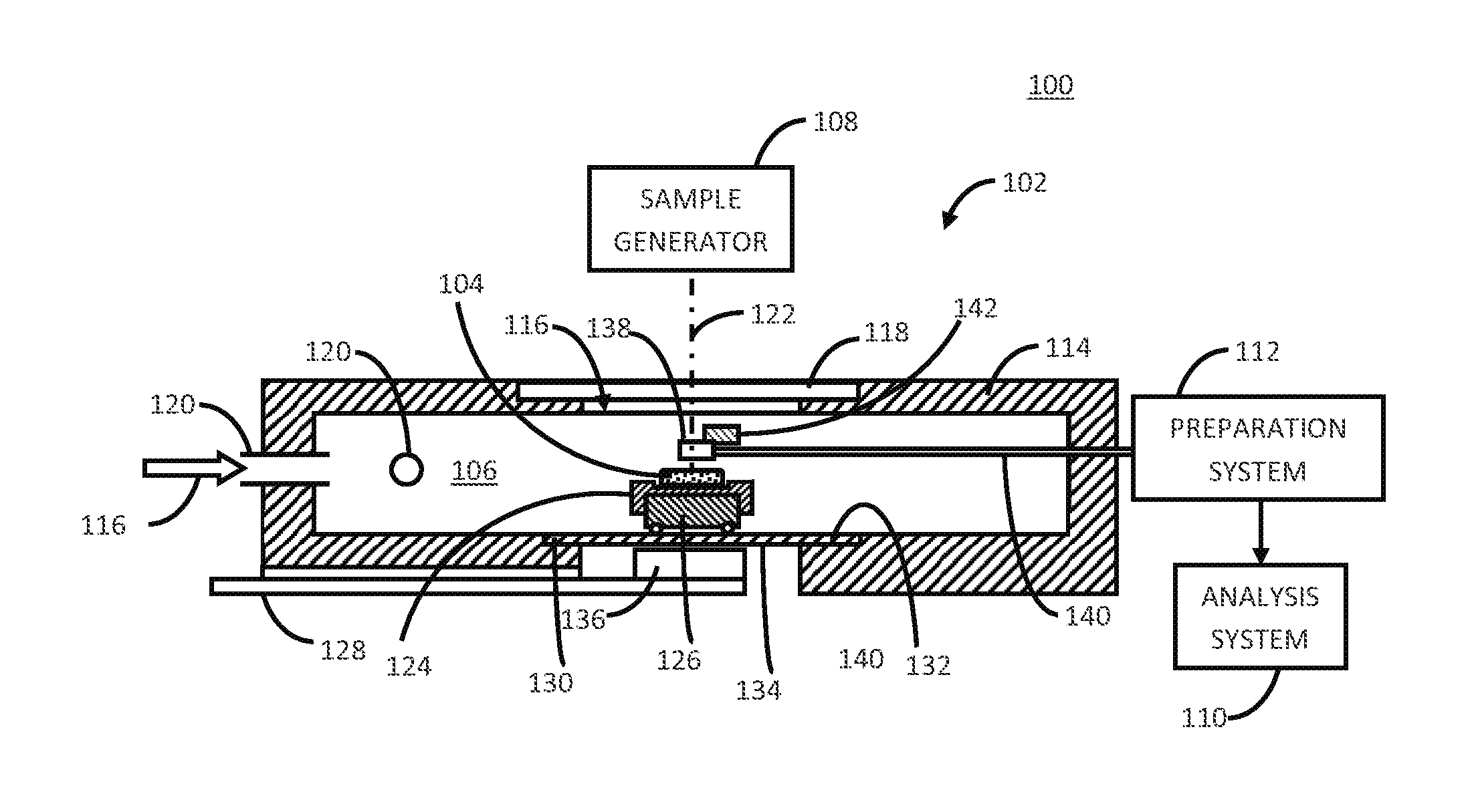
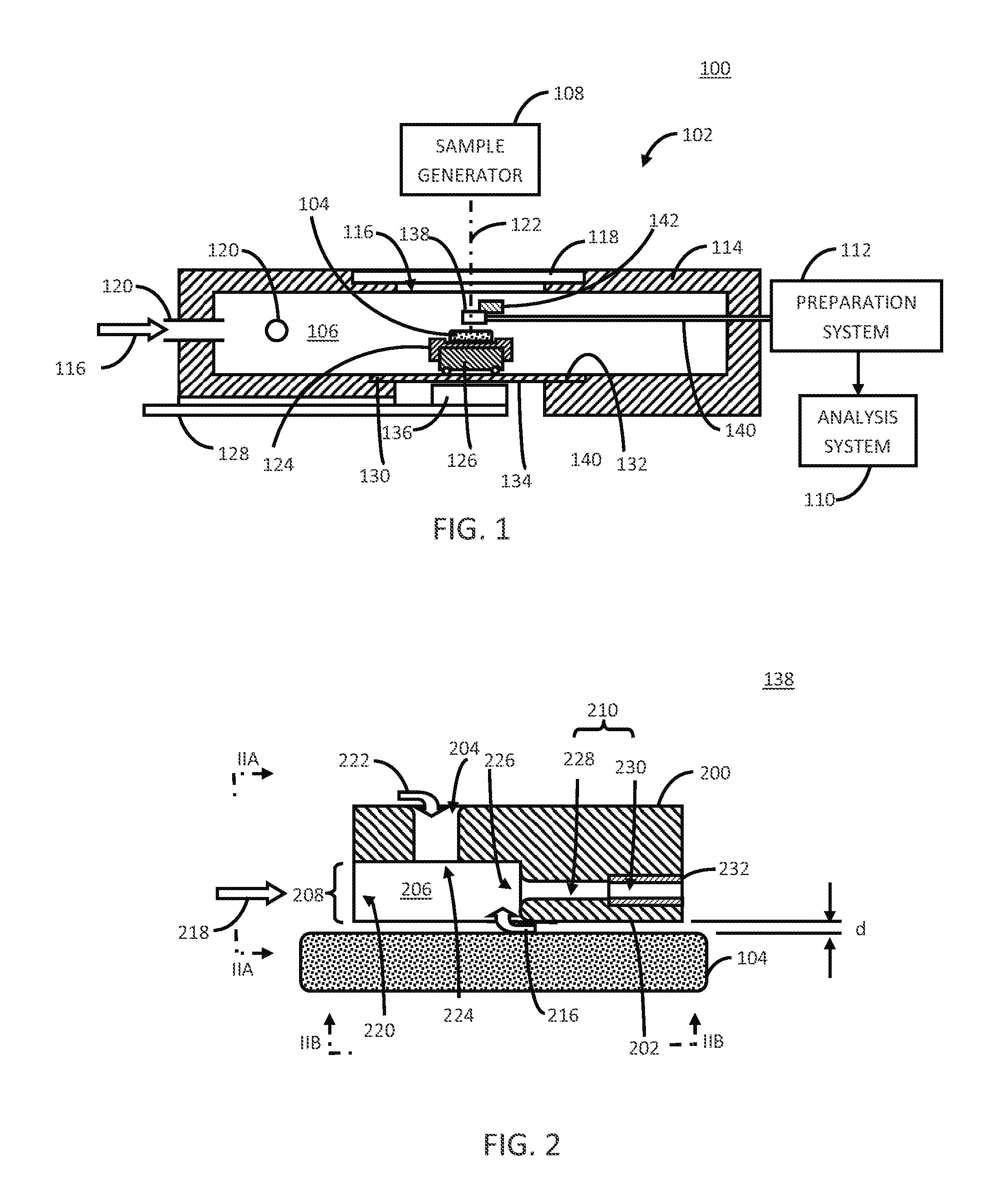
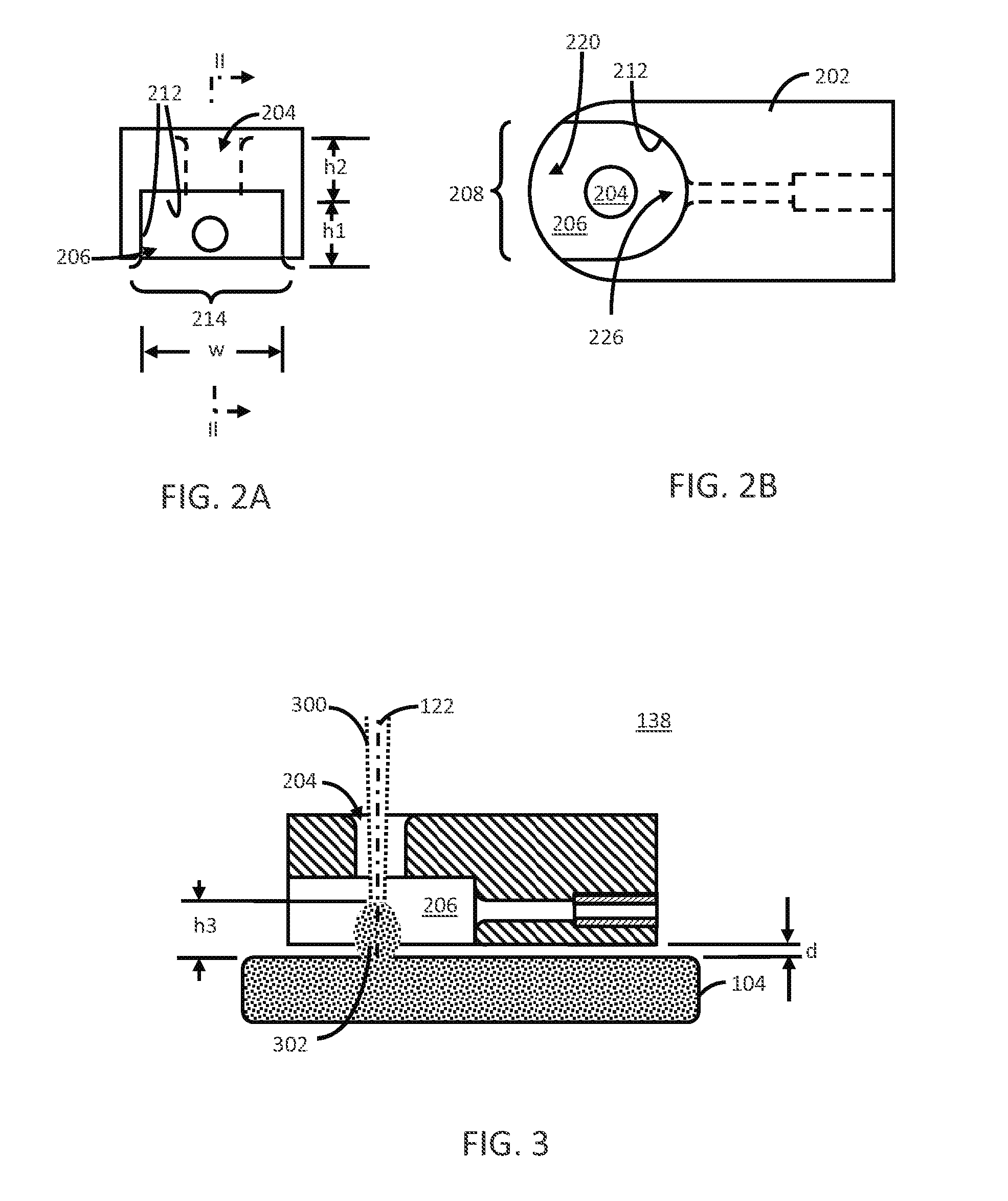
[0029]The following description will typically be with reference to specific structural embodiments and methods. It is to be understood that there is no intention to-be limited to the specifically disclosed embodiments and methods but that other features, elements, methods and embodiments may be used for implementations of this disclosure. Preferred embodiments are described to illustrate the technology disclosed, not to limit its scope, which is defined by the claims. Those of ordinary skill in the art will recognize a variety of equivalent variations on the description that follows. Unless otherwise stated, in this application specified relationships, such as parallel to, aligned with, or in the same plane as, mean that the specified relationships are within limitations of manufacturing processes and within manufacturing variations. When components are described as being coupled, connected, being in contact or contacting one another, they need not be physically directly touching o...


PUM


Abstract

A method for reducing thermal effects in laser ablation optical emission spectrometry includes creating discrete ablation spots along an analysis line on a target surface. At least one of the following is also carried out. First, the ablation spots are positioned so that a pair of successive ablation spots are spaced apart from one another along the analysis line and are separated from one another by another ablation spot. Second, when the analysis line comprises generally parallel, adjacent analysis line segments, the ablation spots are positioned so that (A) a pair of successive ablation spots are on different analysis line segments, and (B) the successive ablation spots are positioned to be at different longitudinal positions along the analysis line segments when the different analysis line segments are adjacent to one another. As a result, a linear scan of isolated ablation spots can be generated.

Description

CROSS-REFERENCE TO OTHER APPLICATIONS[0001]This application claims the benefit of U.S. provisional patent application No. 61 / 791,502, filed 15 Mar. 2013, the disclosure of which is incorporated by reference.BACKGROUND OF THE INVENTION[0002]Laser ablation Inductively Coupled Plasma Mass Spectrometry (LA-ICP-MS) or Laser ablation Inductively Coupled Plasma Optical Emission Spectrometry (LA-ICP-OES) techniques can be used to analyze the composition of a target (e.g., a solid or liquid target material). Often, a sample of the target is provided to an analysis system in the form of an aerosol (i.e., a suspension of solid and possibly liquid particles and / or vapor in a carrier gas, such as helium gas). The sample is typically produced by arranging the target within a laser ablation chamber, introducing a flow of a carrier gas within the chamber, and ablating a portion of the target with one or more laser pulses to generate a plume containing particles and / or vapor ejected or otherwise gen...

Claims


Application Information

Patent Timeline
IPC IPC(8): G01J3/443
CPCG01J3/443G01N21/718H05H1/30H01J49/0463
Inventor O'CONNOR, CIARAN JOHN PATRICK
Owner ELEMENTAL SCI LASERS LLC
Learn More