
Formation and Stability of Cu-Mn Spinel Phase for ZPGM Catalyst Systems

a catalyst system and spinel phase technology, applied in the field of catalyst systems, can solve the problems of reducing the effective surface area, increasing the cost, and gradual degradation of the catalytic function, and achieve the effect of optimal spinel phase formation and phase stability properties

Inactive Publication Date: 2014-09-18
CLEAN DIESEL TECHNOLOGIES
View PDF3 Cites 27 Cited by
  • Summary
  • Abstract
  • Description
  • Claims
  • Application Information

AI Technical Summary

Benefits of technology

The patent describes how to make certain materials called Cu-Mn spinel, which can be used as catalysts in underfloor and closed-loop coupled catalyst applications. The patent seeks to determine the ideal ratio of copper to manganese in the spinel structure for each application, as this can affect the performance and durability of the catalyst. The patent also discusses the process of preparing the spinel materials by forming bulk powder samples with different ratios of copper and manganese and analyzing them using X-ray diffraction. This analysis helps to determine the stability of the spinel phase and the effect of temperature on crystallite size. The patent concludes that the formation and stability of the spinel phase can provide an indication of the stability of the catalyst during operation, and that the chemical composition of the spinel materials can enhance their stability at high temperatures. This information is important for manufacturers to improve the performance and flexibility of the catalysts.

Problems solved by technology

Currently, at higher temperatures at which the catalyst functions, the catalytic centers become massed together or agglomerated, which in turn decreases the effective surface area to result in the gradual degradation of the catalytic functions.
Catalyst systems are generally fabricated using platinum group metals (PGM) which are characterized by a small market circulation volume, constant fluctuations in price, and constant risk to stable supply, variables that drive up their cost.

Method used


Image

  • Formation and Stability of Cu-Mn Spinel Phase for ZPGM Catalyst Systems
  • Formation and Stability of Cu-Mn Spinel Phase for ZPGM Catalyst Systems
  • Formation and Stability of Cu-Mn Spinel Phase for ZPGM Catalyst Systems

Examples


example # 1

Example #1

Cu0.2Mn2.8O4 Bulk Powder

[0047]Cu—Mn solution may be prepared by mixing the appropriate amount of Mn nitrate solution (MnNO3) and Cu nitrate solution (CuNO3), with water to make solution at specific molar ratio according to formulation CuxMn3-xO4, in which X may take values of 0.2. For preparation of Cu0.2Mn2.8O4 bulk powder, after precipitation of Cu—Mn solution with appropriate base solution, the slurry may undergo filtering and washing followed by drying calcination at a plurality of temperatures of about 700° C., 900° C., and 1,100° C. for about 5 hours. The prepared powder at different calcination temperatures may be subsequently ground to fine grain to form bulk powder.

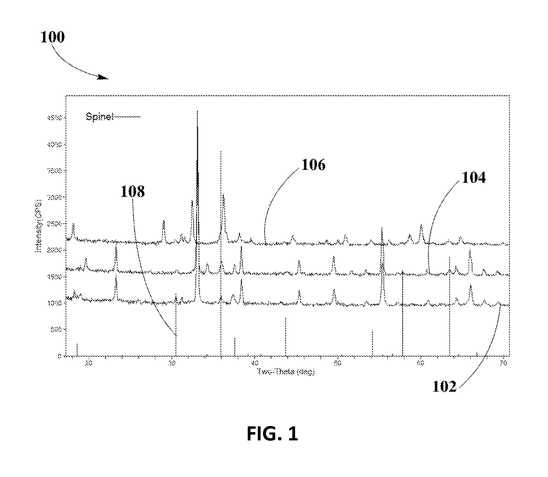
[0048]FIG. 1 shows XRD analysis 100 for spinel phase formation and spinel phase stability of Cu0.2Mn2.8O4 spinel in example #1, at different firing temperatures, according to an embodiment. XRD spectrum 102 shows Cu0.2Mn2.8O4 spinel calcined at temperature of about 700° C., XRD spectrum 104 shows Cu0.2M...

example # 2

Example #2

Cu0.5Mn2.5O4 Bulk Powder

[0051]Cu—Mn solution may be prepared by mixing the appropriate amount of Mn nitrate solution (MnNO3) and Cu nitrate solution (CuNO3), with water to make solution at specific molar ratio according to formulation CuxMn3-xO4, in which X may take values of 0.5. For preparation of Cu0.5Mn2.5O4 bulk powder, after precipitation of Cu—Mn solution with appropriate base solution, the slurry may undergo filtering and washing followed by drying calcination at a plurality of temperatures of about 600° C., 800° C., 900° C., 1000° C. and 1,100° C. for about 5 hours. The prepared powder at different calcination temperatures may be subsequently ground to fine grain to form bulk powder.

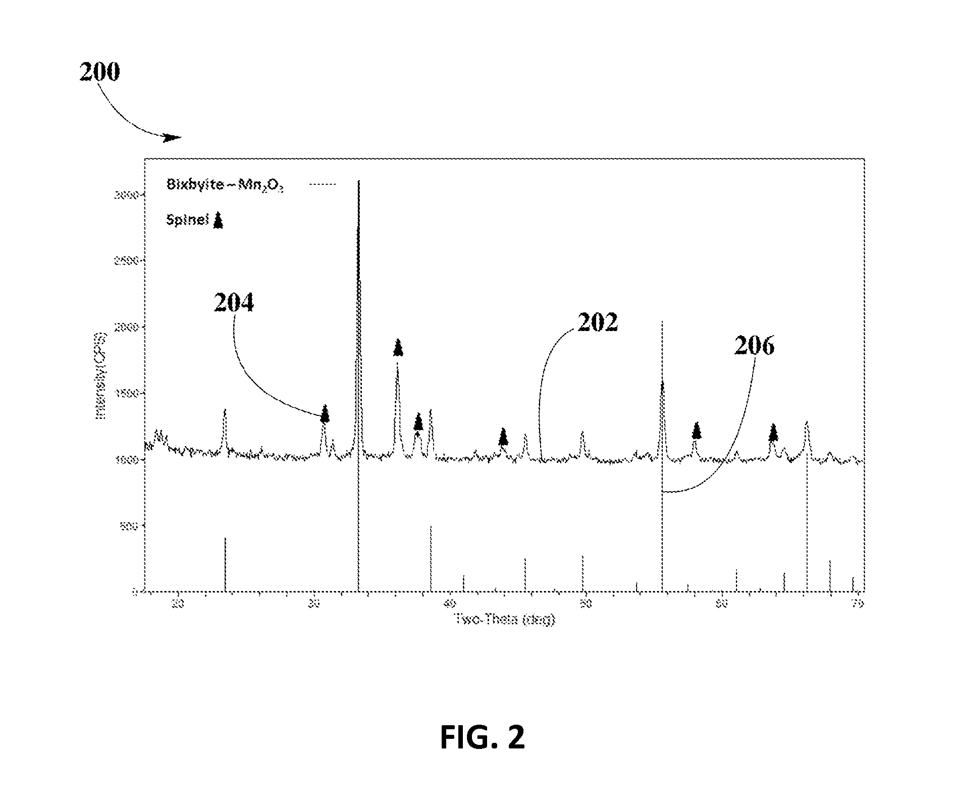
[0052]FIG. 2 depicts XRD analysis 200 for spinel phase formation of Cu0.5Mn2.5O4 spinel in example #2, fired at about 600° C., according to an embodiment.

[0053]XRD spectrum 202 shows that Cu—Mn spinel forms in sample of Cu0.5Mn2.5O4 calcined at about 600° C. Solid triangle markers 204 ...

example # 3

Example #3

Cu1.0Mn2.0O4 bulk powder

[0061]Cu—Mn solution may be prepared by mixing the appropriate amount of Mn nitrate solution (MnNO3) and Cu nitrate solution (CuNO3), with water to make solution at specific molar ratio according to formulation CuxMn3-xO4, in which X may take values of 1.0. For preparation of Cu1.0Mn2.0O4 bulk powder, after precipitation of Cu—Mn solution with appropriate base solution, the slurry may undergo filtering and washing followed by drying calcination at a plurality of temperatures of about 600° C., 800° C., 900° C., 1,000° C. and 1,100° C. for about 5 hours. The prepared powder at different calcination temperatures may be subsequently ground to fine grain to form bulk powder.

[0062]FIG. 6 shows XRD analysis 600 for spinel phase formation of Cu1.0Mn2.0O4 spinel in example #3, calcined at about 600° C., according to an embodiment.

[0063]XRD spectrum 602 shows that stable Cu—Mn spinel phase forms in sample of Cu1.0Mn2.0O4 calcined at about 600° C. Solid lines ...


PUM

PropertyMeasurementUnit
temperaturesaaaaaaaaaa
voltageaaaaaaaaaa

Abstract

Optimized Cu—Mn spinel compositions, with optimal spinel phase formation and phase stability properties, for a plurality of ZPGM catalysts in underfloor and closed-loop coupled catalyst applications are disclosed. Plurality of Cu—Mn spinel compositions are prepared with variations of molar ratios. Effect of calcination temperature is analyzed to determine spinel phase formation and phase stability, as well as the effect of calcination temperature on lattice parameter of spinel, as correlated to spinel phase formation and phase stability of optimal Cu—Mn spinel compositions disclosed. Disclosed Cu—Mn spinels with enhanced spinel phase formation and phase stability may be suitable for ZPGM catalyst systems used in a vast number of TWC applications.

Description

CROSS-REFERENCE TO RELATED APPLICATIONS[0001]This application is a continuation-in-part of U.S. patent application Ser. Nos. 13 / 849,169 and 13 / 849,230, filed Mar. 22, 2013, respectively, and claims priority to U.S. Provisional Application Nos. 61 / 791,721 and 61 / 791,838, filed Mar. 15, 2013, respectively, and is related to U.S. patent application Ser. No. 14 / 090,861, filed Nov. 26, 2013, entitled System and Methods for Using Synergized PGM as a Three-Way Catalyst.BACKGROUND[0002]1. Technical Field[0003]This disclosure relates generally to catalyst systems, and, more particularly, to formation of Cu—Mn spinel phase and thermal stability of Cu—Mn spinel for use in Zero Platinum Group Metal (ZPGM) catalyst systems.[0004]2. Background Information[0005]Regulatory standards for acceptable emissions are continually revised in response to human health issues and air-quality concerns. Strict-compliance regulatory standards have been adopted worldwide to control emissions of oxides of nitrogen...

Claims


Application Information

Patent Timeline
Patent Type & Authority Applications(United States)
IPC IPC(8): B01J23/889
CPCB01J23/8892B01D53/945B01D2255/2073B01D2255/20761B01D2255/405B01D2255/65B01J23/005B01J37/03B01J2523/00Y02T10/12B01J2523/17B01J2523/48B01J2523/56B01J2523/72
Inventor NAZARPOOR, ZAHRAGOLDEN, STEPHEN J.
Owner CLEAN DIESEL TECHNOLOGIES
Learn More