Dynamic range extension systems and methods for particle analysis in blood samples

a technology of dynamic range extension and particle analysis, which is applied in the field of dynamic range extension systems and methods for particle analysis in blood samples, can solve the problems of blood cell or fragment smaller than a normal plt, difficult to detect and count accurately in a particle counter, and difficulty in rbcs and plts to accurately count, so as to facilitate the flow of a sample stream and reduce the size of the flowpath

Active Publication Date: 2014-09-18
IRIS INT
View PDF7 Cites 29 Cited by
  • Summary
  • Abstract
  • Description
  • Claims
  • Application Information

AI Technical Summary

Benefits of technology

[0031]In another aspect, embodiments of the present invention encompass systems for measuring a quantity of a first cell type in a blood fluid sample. The sample can include a second cell type. Exemplary systems include a hematology cell counter having a channel and an output, the output operatively coupled to the channel so as to generate signals indicative of a population of the second cell type in a first volume of the sample flowing through the channel, a flowcell configured to facilitate flow of a sample stream, the sample stream having a second volume of the sample and a sheath fluid, and having a thickness and a width greater than the thickness, an imaging apparatus configured to acquire images of a first number of the first type cells and a second number of the second type cells, the acquired images being acquired along an image path traversing the thickness of the sample stream, a processor, an image analysis module having a tangible medium embodying machine-readable code executed on the processor for determining a ratio of the first n

Problems solved by technology

For example, a particle such as a blood cell or fragment smaller than a normal PLT (i.e., having a diameter less than 2 μm) may be difficult to detect and count accurately in a particle counter.
An abnormal cell larger than a regular white cell (i.e., having a diameter higher than 15 μm) may be difficult to detect and count accurately in a particle counter.
In additi

Method used


Image

  • Dynamic range extension systems and methods for particle analysis in blood samples
  • Dynamic range extension systems and methods for particle analysis in blood samples
  • Dynamic range extension systems and methods for particle analysis in blood samples

Examples


Embodiment Construction

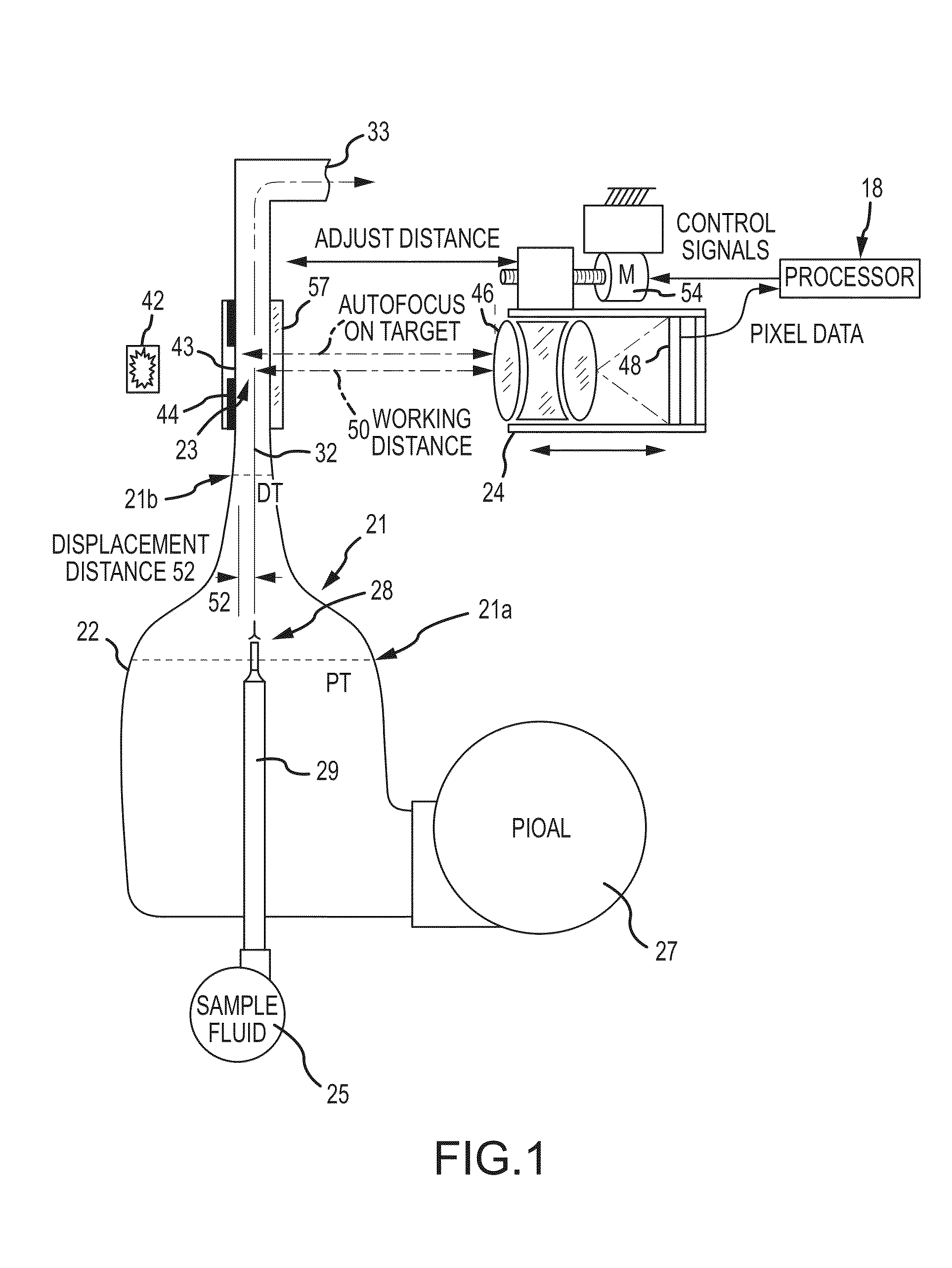
[0052]The present disclosure relates to apparatus, systems, compositions, and methods for analyzing a sample containing particles. In one embodiment, the invention relates to an automated particle imaging system which comprises an analyzer which may be, for example, a visual analyzer. In some embodiments, the visual analyzer may further comprise a processor to facilitate automated analysis of the images.

[0053]According to this disclosure, a system comprising a visual analyzer is provided for obtaining images of a sample comprising particles suspended in a liquid. The system may be useful, for example, in characterizing particles in biological fluids, such as detecting and quantifying erythrocytes, reticulocytes, nucleated red blood cells, platelets, and white blood cells, including white blood cell differential counting, categorization and subcategorization and analysis. Other similar uses such as characterizing blood cells from other fluids are also contemplated.

[0054]The discrimin...


PUM


Abstract

For analyzing a sample containing particles of at least two categories, such as a sample containing blood cells, a particle counter subject to a detection limit is coupled with an analyzer capable of discerning particle number ratios, such as a visual analyzer, and a processor. A first category of particles can be present beyond detection range limits while a second category of particles is present within respective detection range limits. The concentration of the second category of particles is determined by the particle counter. A ratio of counts of the first category to the second category is determined on the analyzer. The concentration of particles in the first category is calculated on the processor based on the ratio and the count or concentration of particles in the second category.

Description

CROSS-REFERENCES TO RELATED APPLICATIONS[0001]This application is a non-provisional of, and claims the benefit of priority to, U.S. Provisional Patent Application No. 61 / 799,152 filed Mar. 15, 2013, the content of which is incorporated herein by reference. This application is also related to U.S. patent application Ser. Nos. 14 / 216,811, 14 / 216,533, 14 / 215,834, and 14 / 216,339, and International Patent Application Nos. PCT / US14 / 30928, PCT / US14 / 30902, PCT / US14 / 30850, and PCT / US14 / 30851, all filed Mar. 17, 2014. The content of each of these filings is incorporated herein by reference.BACKGROUND OF THE INVENTION[0002]This disclosure relates to the field of apparatus, systems, compositions, and methods for analysis of particles, including imaging of particles in fluid samples, using wholly or partly automated devices to discriminate and quantify particles such as blood cells in the sample. The present disclosure also relates to a particle and / or intracellular organelle alignment liquid (P...

Claims


Application Information

Patent Timeline
IPC IPC(8): G01N33/80
CPCG01N33/80G01N2015/1452G01N15/1468G01N2015/0065G01N2015/1037G01N2015/1411G01N2015/1413G01N2015/1486G01N15/1434G01N15/147G01N15/1463G01N15/1475G01N21/53G01N2021/058G01N1/30G01N15/1404G01N33/49G01N33/4915G01N33/5094G01N15/06G01N15/1459G01N15/1429G01N2015/1481G02B21/244G06T7/0012G06T2207/10148G02B7/28G01N2015/144G01N15/1436G02B7/36G01N33/5091
Inventor ADAMS, THOMAS H.WANDERS, BART J.ROCHE, JOHNKASDAN, HARVEY L.
Owner IRIS INT
Why Eureka
Try Eureka