Automatic continuous a-mode ultrasound monitor for pneumothorax

a technology of ultrasound monitor and pneumothorax, which is applied in the direction of application, ultrasonic/sonic/infrasonic image/data processing, ultrasonic/sonic/infrasonic diagnostics, etc., can solve the problems of life-threatening, large growing pneumothorax, and collapse of the lungs, so as to monitor the development and/or the progress of pneumothorax in a reliable, accurate and particularly simple fashion

Inactive Publication Date: 2014-09-18
UNIV OF FLORIDA RES FOUNDATION INC
View PDF4 Cites 20 Cited by
  • Summary
  • Abstract
  • Description
  • Claims
  • Application Information

AI Technical Summary

Benefits of technology

[0008]The subject invention automatically and continuously monitors the development and/or p

Problems solved by technology

This causes the lungs to collapse and can be life threatening.
Large growing pneumothorax is life threatening and usually a chest tube is inserted to evacuate air.
In certain instances, complications may arise from the treatment of pneumothorax, including death.
The dilemma with pneumothorax is that it can be difficult to diagnose and difficult to monitor, particularly pneumothorax progression.
Except for visualization of gross violation of the chest cavity, palpation of chest wall crepitance (from pleural air entering the chest subcutaneous tissue), palpation of flail chest wall segments, or visualization of tracheal deviation, the physical exam is extraordinarily limited in its ability to diagnose most pneumothoraces.
Auscultation of the chest to identify absent or diminished breath sounds and/or perc

Method used


Image

  • Automatic continuous a-mode ultrasound monitor for pneumothorax
  • Automatic continuous a-mode ultrasound monitor for pneumothorax
  • Automatic continuous a-mode ultrasound monitor for pneumothorax

Examples


example 1

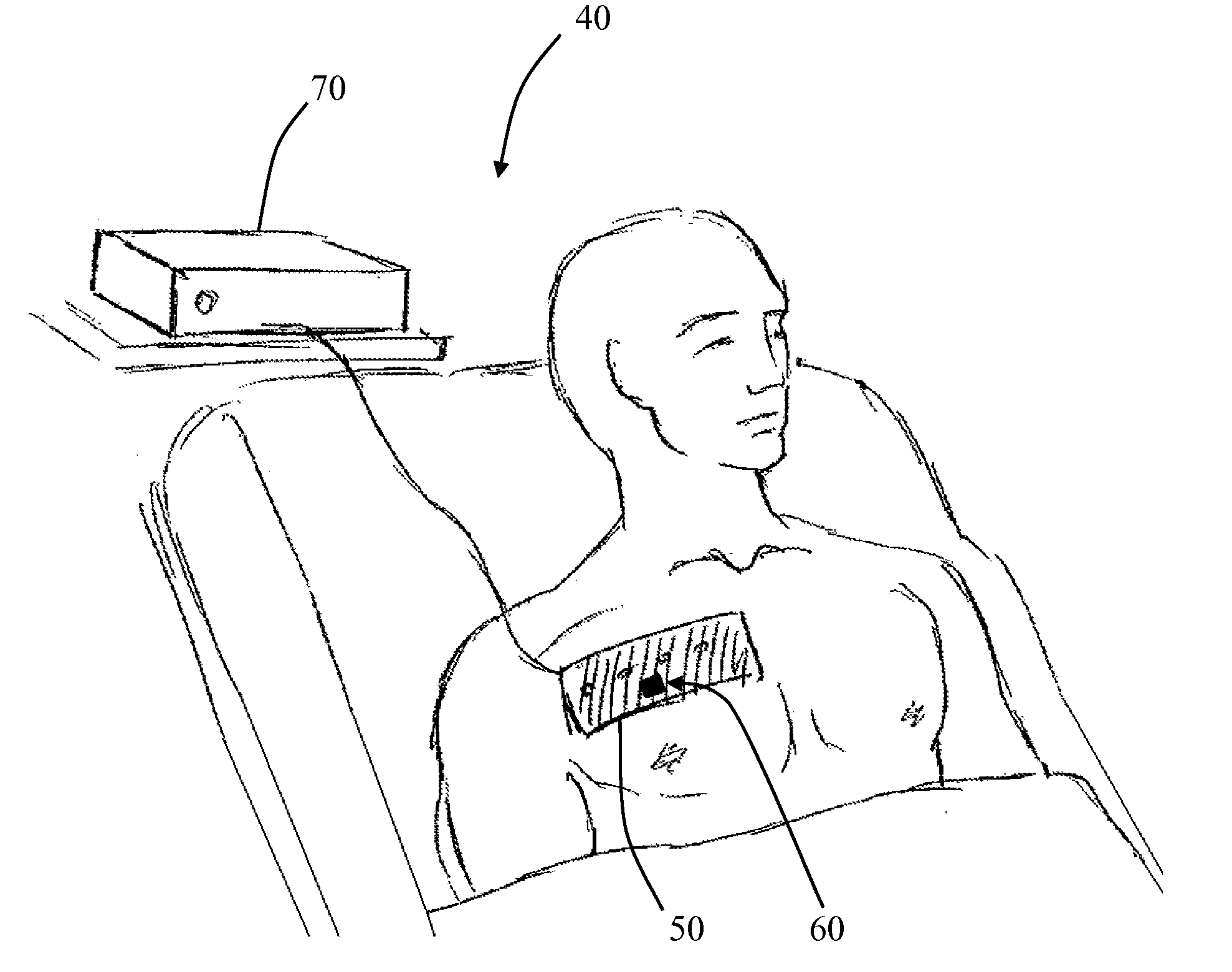
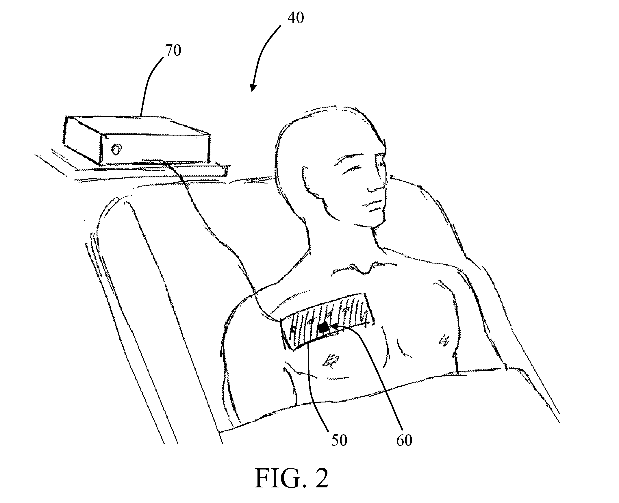
[0040]FIGS. 2 and 3 are illustrations a pneumothorax monitoring system 40 of the invention. An ultrasound patch 50 is provided. The ultrasound patch includes an ultrasound sensor 60. The ultrasound patch 50 may be directly wired to a processing system 70 (FIG. 2). Alternatively, the ultrasound patch 50 includes wireless media 75 for communicating with the processing system 70 (FIG. 3).

[0041]FIG. 4 is a cross section depiction of the ultrasound patch 50 as it is applied to the chest of a patient. Specifically, the ultrasound sensor 60 comprises transducers 80 and a receiver 85 for generating A-mode ultrasound return signals to be monitored and analyzed by the processing system 70. The ultrasound patch 50 is applied to the skin 90 of the patient. The signals generated by the ultrasound sensor 60 will be representative of the ultrasound that travels through the skin 90, chest wall 95, parietal pleura 100, visceral pleura 105 and lung 110.

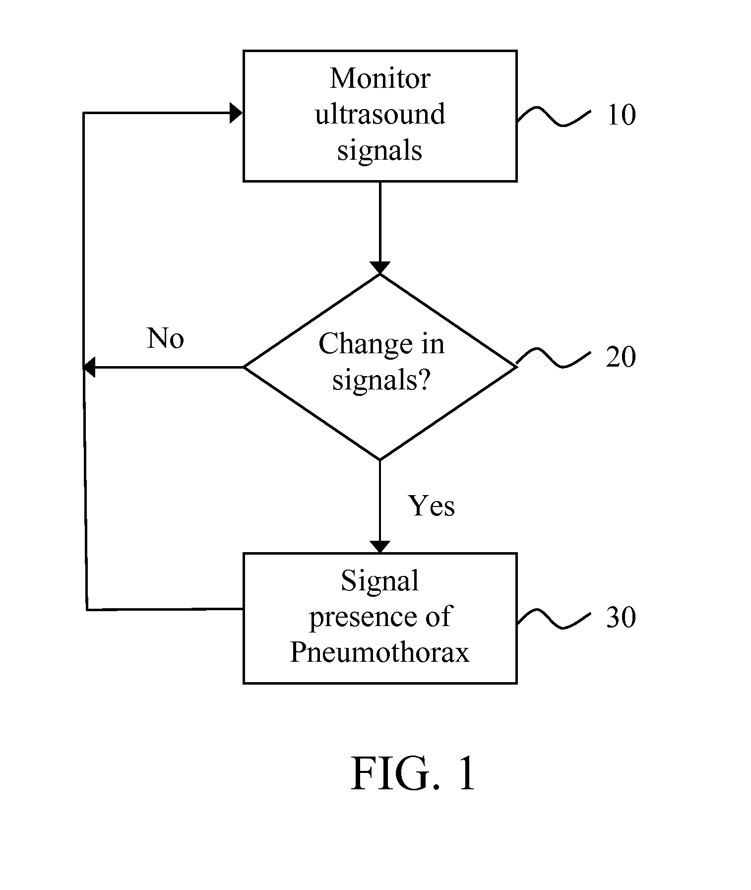
[0042]The system 40 would monitor the detection ...


PUM


Abstract

Automated continuous analysis of ultrasound data is provided to determine occurrence of pneumothorax in a patient. Specifically, A-mode ultrasound data is processed by a processing system to identify automatically if pneumothorax has occurred in a patient.

Description

CROSS-REFERENCE TO A RELATED APPLICATION[0001]This application claims the benefit of U.S. provisional application Serial No. 61 / 791,933 filed Mar. 15, 2013, which is incorporated herein by reference in its entirety.BACKGROUND OF INVENTION[0002]“Pneumothorax” refers to when air enters the pleural space between the lungs and the chest wall. In healthy individuals, this space is under negative pressure, so that the lungs can expand with the chest to breath. This pressure becomes positive when air enters the pleural space. This causes the lungs to collapse and can be life threatening. It is most often caused by blunt trauma to the chest, such as the trauma experienced in some car accidents. Pneumothorax can also develop as a complication following certain medical procedures, such as central venous catheter placement, mechanical ventilation, nerve blockade, etc.[0003]Treatment of pneumothorax depends on the size of pneumothorax and its dynamic. Large growing pneumothorax is life threaten...

Claims


Application Information

Patent Timeline
IPC IPC(8): A61B8/08A61B8/00
CPCA61B8/5223A61B8/08A61B8/56A61B8/4483A61B8/4236A61B5/08A61B5/6823G16H50/30
Inventor KILEY, SEAN P.IHNATSENKA, BARYS VALERIEVICH
Owner UNIV OF FLORIDA RES FOUNDATION INC
Why Eureka
Try Eureka