
Inferred engine local temperature estimator

a local temperature estimator and engine technology, applied in the direction of machines/engines, mechanical equipment, cylinders, etc., can solve the problems of inadvertent waste of useful energy, increased production cost, and low cost alternatives, so as to reduce production cost, reduce the effect of concerns related to traditional hardware sensor robustness over time and reduce the cost of production

Active Publication Date: 2014-09-25
FORD GLOBAL TECH LLC
View PDF5 Cites 28 Cited by
  • Summary
  • Abstract
  • Description
  • Claims
  • Application Information

AI Technical Summary

Benefits of technology

The patent proposes a system and method for operating a coolant pump that is independent of engine speed and adjusts parameters based on an inferred local temperature in the exhaust valve bridge of a cylinder head. This approach uses a trained neural network model to estimate the temperature, which allows the system to manage the thermal load on the engine effectively and utilize flow devices to their full potential. This method reduces the cost of production, allows for real-time characterization of parameters, and improves the robustness of the system over time. Additionally, it reduces the use of storage and computational resources in the powertrain control module.

Problems solved by technology

Inferential sensors offer low cost alternatives for signal acquisition compared to hardware sensors whose inclusion may be difficult to implement in an engine in some instances.
Furthermore, hardware sensors often indicate a bulk engine temperature that relates to an energy potential between a source and sink within the engine system and so do not capture the thermal state of certain engine regions, like the region near a combustion chamber, which can have a higher temperature and therefore exceed thresholds well before bulk temperature regions.
When this is the case, useful energy may be inadvertently wasted that results in a suboptimal thermal management process.
In addition, the approach described allows a low cost alternative compared to methods that use a sensor directly in the region of the cylinder head, which presents packaging difficulties in the engine compartment and thereby increases the cost of production.

Method used


Image

  • Inferred engine local temperature estimator
  • Inferred engine local temperature estimator
  • Inferred engine local temperature estimator

Examples


Embodiment Construction

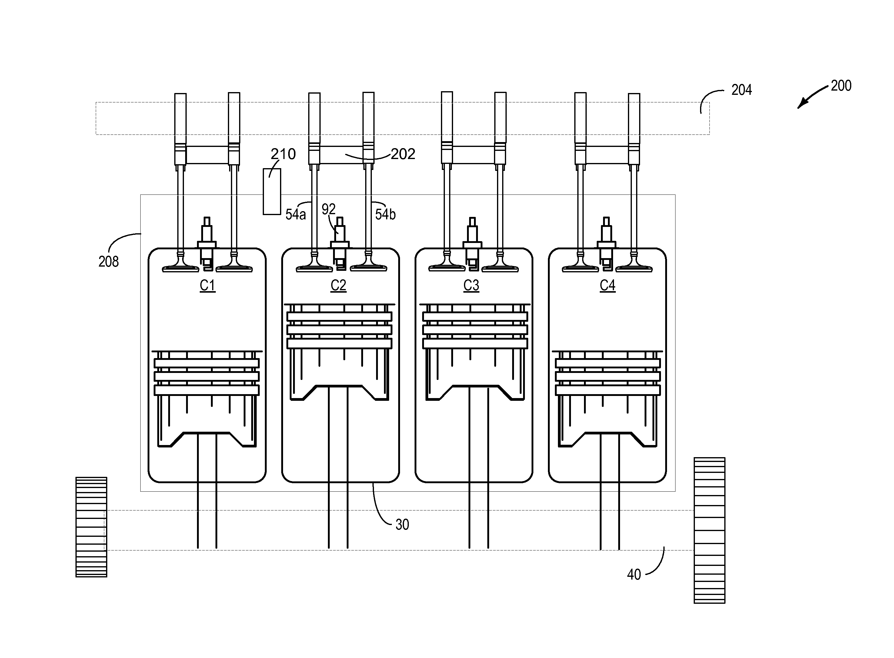
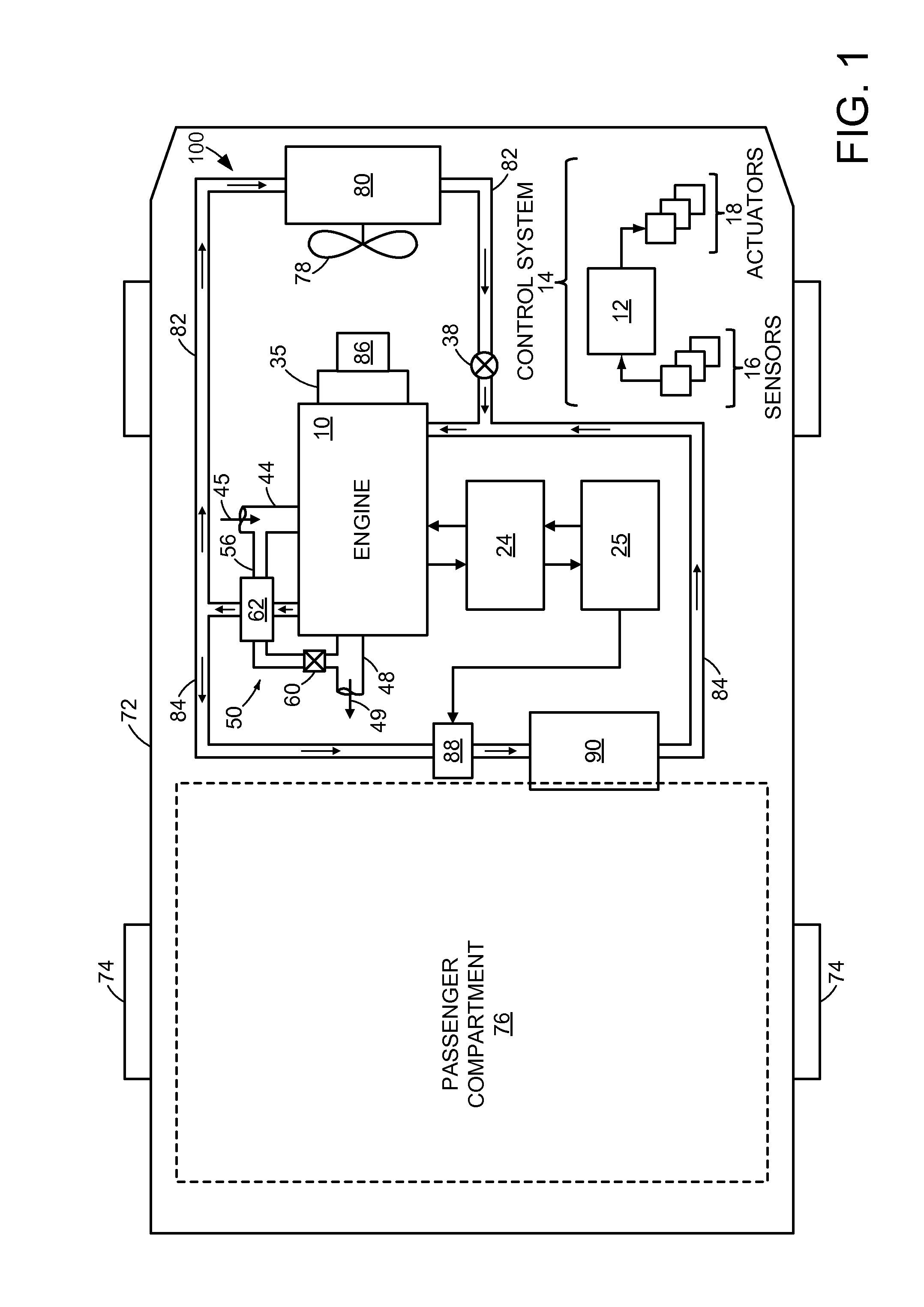
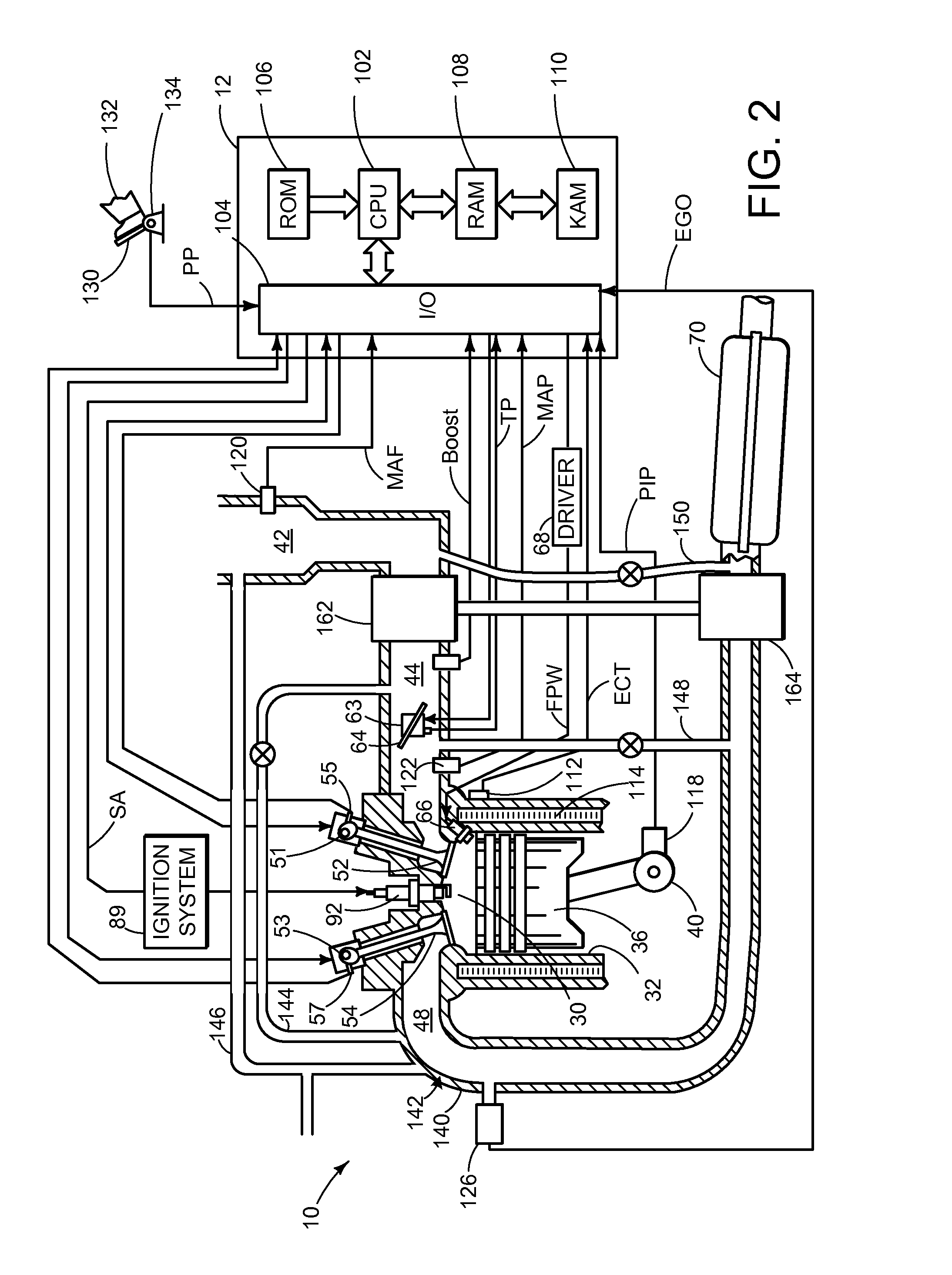
[0015]The present description relates to a method for estimating a temperature in an engine system. In the example embodiment provided, the method is used to estimate a local metal temperature in an exhaust valve bridge where placement of a temperature sensor is difficult. Because the inferential method depends on engine parameters and operating conditions within the engine system, a schematic diagram of an example vehicle is shown in FIG. 1. Then, in FIGS. 2 and 3, schematic diagrams of example engine cylinders are shown to illustrate various features in accordance with the present disclosure. In FIG. 4, a top view of the engine bank is shown to further illustrate where the example local temperature is estimated relative to an example temperature sensor that measures a bulk temperature therein. Turning to control of the method, FIG. 5 shows a flow chart illustrating how one or more operating parameters may be adjusted based on the estimated temperature. Then, FIG. 6 illustrates how...


PUM


Abstract

A system and methods for inferring a local engine temperature based on various engine conditions input to a dynamic model are disclosed. In the example system provided, an inferential temperature sensor uses a trainable model to estimate a local metal temperature in an exhaust valve bridge of a cylinder head which thereby allows closed loop control of a coolant flow device independent from engine speed, engine state, coolant flow state or system temperature. In response to estimated local metal temperatures, the methods described further allow thermal management of the engine system to be optimized.

Description

FIELD[0001]The present description relates to a system and method for estimating a temperature in an engine system. The system and method may be particularly useful for estimating a local metal temperature in an exhaust valve bridge of a cylinder head.BACKGROUND AND SUMMARY[0002]Inferential sensors offer low cost alternatives for signal acquisition compared to hardware sensors whose inclusion may be difficult to implement in an engine in some instances. Furthermore, hardware sensors often indicate a bulk engine temperature that relates to an energy potential between a source and sink within the engine system and so do not capture the thermal state of certain engine regions, like the region near a combustion chamber, which can have a higher temperature and therefore exceed thresholds well before bulk temperature regions. When this is the case, useful energy may be inadvertently wasted that results in a suboptimal thermal management process.[0003]In one example system, U.S. Pat. No. 7...

Claims


Application Information

Patent Timeline
Patent Type & Authority Applications(United States)
IPC IPC(8): F01P5/12
CPCF01P5/12F01P7/167F01P3/20F01P7/162F01P2025/32F01P2025/33F01P2025/62F02B25/14F02B33/04F02B61/045F02B2075/025F02F1/22
Inventor ABOU-NASR, MAHMOUDBUCKMAN, COLBY JASONFILEV, DIMITAR PETROV
Owner FORD GLOBAL TECH LLC
Learn More