Reluctance motor

a technology of resistance motor and resistance current, which is applied in the direction of synchronous motor, magnetic circuit rotating parts, magnetic circuit shape/form/construction, etc., can solve the problems of weakened electromagnetic force, inability to efficiently generate induced current, and difficulty in obtaining large torque, etc., to achieve high efficiency and improve torque

Active Publication Date: 2014-09-25
SUZUKI MOTOR CORP
View PDF11 Cites 19 Cited by
  • Summary
  • Abstract
  • Description
  • Claims
  • Application Information

AI Technical Summary

Benefits of technology

[0013]Therefore, an object of the invention is to provide a reluctance motor which can collect loss energy to achieve

Problems solved by technology

Each of the reluctance motors has a problem that it is difficult to obtain large torque when the reluctance motor is of a type using only reluctance torque, in comparison with a motor (electric motor) of a type which is driven by use of magnet torque generated by permanent magnets embedded on the rotor side.
Accordingly, magnetic interference takes place so that the induced c

Method used


Image

  • Reluctance motor
  • Reluctance motor
  • Reluctance motor

Examples


Embodiment Construction

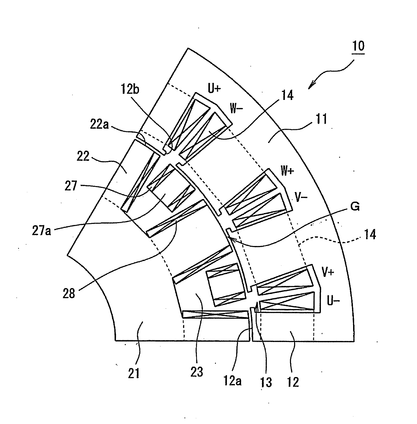
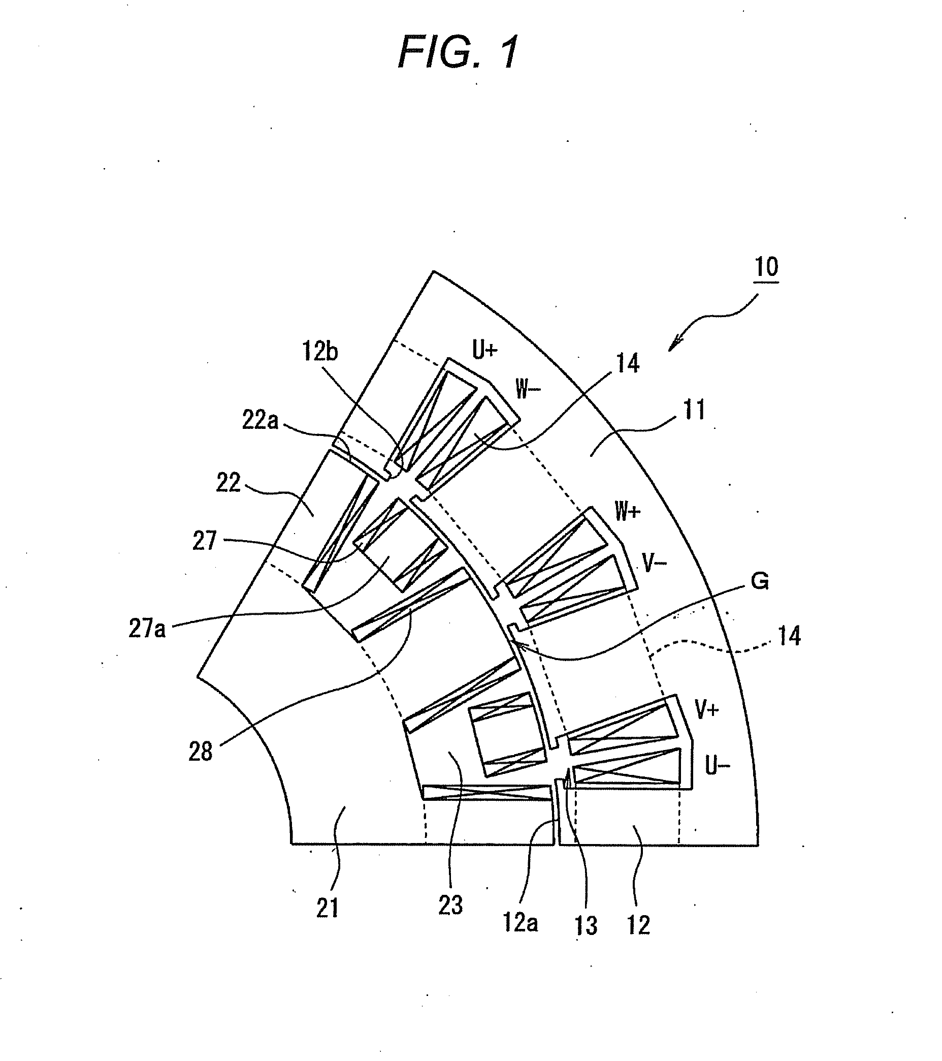
[0063]An embodiment of the invention will be described in detail below with reference to the drawings. FIGS. 1 to 21 are views for explaining an embodiment of a reluctance motor according to the invention. FIGS. 1 to 3 are radially sectional views of reluctance motors, each of which is depicted correspondingly to a mechanical angle of 60° around the axis thereof. The reluctance motor is manufactured to have a structure in which the depicted part corresponding to the mechanical angle of 60° is repeated periodically circumferentially.

[0064]In FIG. 1, a reluctance motor 10 starts at a reluctance motor 10B having a basic structure shown in FIG. 2 and uses a structure in which the problem inherent in a reluctance motor 10D shown in FIG. 3 and developed from the reluctance motor 10B can be solved. For example, the reluctance motor 10 has suitable performance when it is mounted as a drive source similar to an internal combustion engine on a vehicle or inside a wheel in a hybrid car or an e...


PUM


Abstract

A reluctance motor has: a stator provided with drive coils to which multiphase drive currents are inputted; and a rotor provided with a plurality of salient poles which receive primary rotating force when magnetic fluxes generated in the drive coils are interlinked with the rotor, and the rotor has: inductor pole coils which are placed on magnetic paths on which spatial harmonic components superimposed on the magnetic fluxes generated in the drive coils are interlinked with the rotor side so that induced currents can be generated in the inductor pole coils due to the spatial harmonic components of the magnetic fluxes; rectifier elements which rectify the induced currents generated in the inductor pole coils; and electromagnet coils as defined herein, and the inductor pole coils and the electromagnet coils do not serve for each other's purposes but are placed on the rotor individually.

Description

CROSS-REFERENCE TO RELATED APPLICATIONS[0001]This application claims the benefit of Japanese Application No. 2013-055860, filed Mar. 19, 2013, in the Japanese Patent Office. All disclosures of the document(s) named above are incorporated herein by reference.BACKGROUND OF THE INVENTION[0002]1. Field of the Invention[0003]The present invention relates to a reluctance motor. Particularly, it relates to a reluctance motor which has a self-excitation function so as to achieve highly efficient rotation.[0004]2. Description of the Related Art[0005]Reluctance motors are mounted as drive sources on various kinds of drive devices. Each of the reluctance motors has a problem that it is difficult to obtain large torque when the reluctance motor is of a type using only reluctance torque, in comparison with a motor (electric motor) of a type which is driven by use of magnet torque generated by permanent magnets embedded on the rotor side.[0006]Particularly, when a motor is mounted on a hybrid ele...

Claims


Application Information

Patent Timeline
IPC IPC(8): H02K3/28
CPCH02K3/28H02K19/12H02K16/04H02K37/02H02K3/527H02K19/26H02K1/246H02K19/30H02K19/28H02K11/042H02K11/0094H02K19/32H02K1/24
Inventor AOYAMA, MASAHIRO
Owner SUZUKI MOTOR CORP
Why Eureka
Try Eureka