High power factor, electrolytic capacitor-less driver circuit for light-emitting diode lamps

a technology of electrolytic capacitors and driver circuits, which is applied in the direction of power conversion systems, electroluminescent light sources, electric devices, etc., can solve the problems of low power efficiency, inability to truly replace incandescent lamps when it comes to performance, and large harmonics in input current drawn from led lamps, so as to improve the overall reliability and lifetime of led lamps, reduce capacitance, and minimize turn-on switching losses

Active Publication Date: 2014-09-25
JAIN PRAVEEN K +1
View PDF10 Cites 12 Cited by
  • Summary
  • Abstract
  • Description
  • Claims
  • Application Information

AI Technical Summary

Benefits of technology

[0010]The power factor conversion subcircuit has an energy storage portion which consists of a tapped inductor (L1) and an energy storage capacitor (C1). The function of the tapped inductor is to: store energy when the switch is on and to discharge its stored energy to the energy storage capacitor when the switch is off, and to provide soft-switching at the turn-on of the switch to minimize turn-on switching losses. The energy storage capacitor is placed between the input of the step-down voltage conversion circuit and the output of one side of the tapped inductor. This topology provides the following particular f...

Problems solved by technology

While incandescent lamps are able to provide excellent light quality and performance, they suffer from very low power efficiency.
Despite saving a significant amount of energy compared to incandescent lamps, because of the commercial electronic circuitry currently used, LED lighting products cannot truly replace incandescent lamps when it comes to performance.
The input current drawn from the LED lamps then contains a significant amount of unwanted h...

Method used


Image

  • High power factor, electrolytic capacitor-less driver circuit for light-emitting diode lamps
  • High power factor, electrolytic capacitor-less driver circuit for light-emitting diode lamps
  • High power factor, electrolytic capacitor-less driver circuit for light-emitting diode lamps

Examples


Embodiment Construction

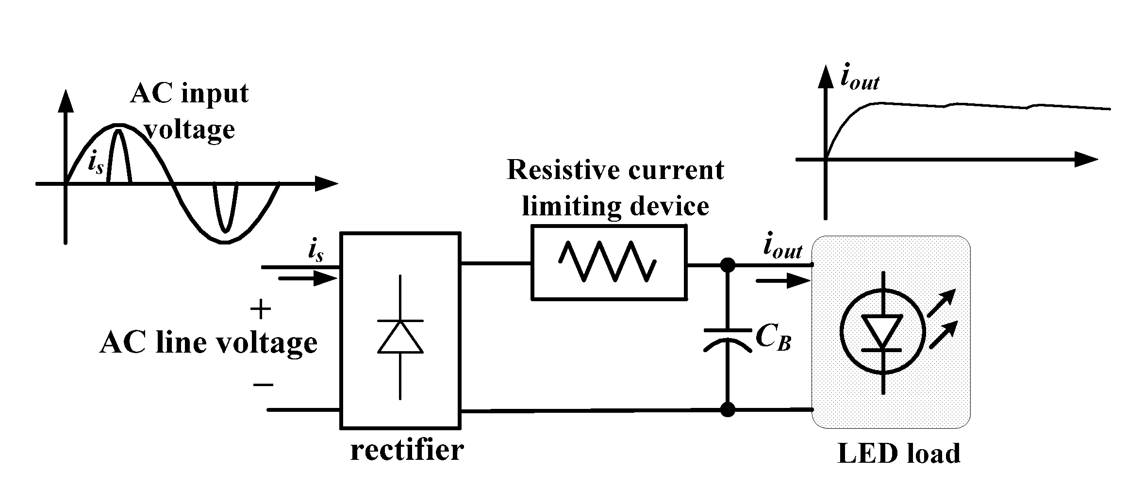
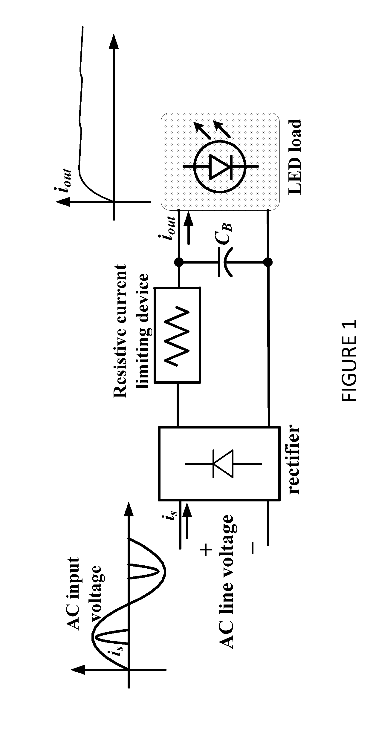
[0056]Referring to FIG. 1, a conventional driver circuit for LED lamps is illustrated. As can be scene, the circuit has a rectifier which receives the AC line voltage input. A resistive current limiting device is also present and a capacitor is present in parallel with the output of the circuit to the LED load. The output current rises until it reaches a steady and relatively constant value.

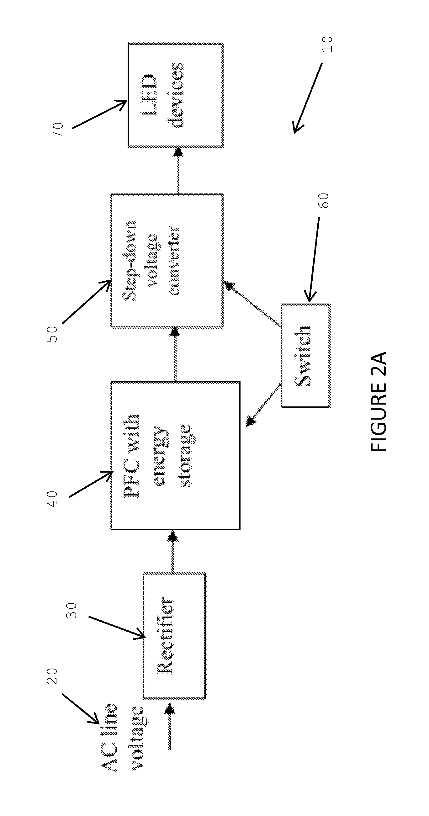
[0057]Referring to FIG. 2A, a block diagram of a circuit according to one aspect of the invention is illustrated. The circuit 10 has an input AC line voltage 20 which is received by a rectifier 30. The rectifier's output is received by a power factor correction (PFC) subcircuit 40 which also has an energy storage capacity. A step down voltage converter or voltage conversion subcircuit 50 receives the output of the PFC subcircuit 40. A switch 60 is coupled to both the PFC subcircuit 40 and voltage conversion subcircuit 50 to provide, when necessary, a path for current to follow.

[0058]Referring to ...


PUM


Abstract

A driver circuit for use with LED lamps. The driver circuit uses a rectifier, a power factor correction subcircuit, a voltage conversion subcircuit, and a semiconductor switch. The power factor correction subcircuit uses a film capacitor instead of an electrolytic capacitor. As well, the power factor correction subcircuit uses either an inductor or a transformer to shape the incoming current to a substantially sinusoidal waveform that is in phase with the input AC current. The semiconductor switch provides a high frequency pulsating triangular current at the output of the rectifier.

Description

RELATED APPLICATIONS[0001]This application is a non-provisional application which claims the benefit of U.S. Provisional Patent Application No. 61 / 803,423 filed Mar. 19, 2013.TECHNICAL FIELD[0002]The present invention relates to driver circuits for light emitting diodes. More specifically, the present invention relates to a high power factor electronic driver circuit for light-emitting diode (LED) lamps and which does not use electrolytic capacitors.BACKGROUND OF THE INVENTION[0003]Lighting is an essential part of every household. Since its invention, incandescent lamps have been illuminating homes around the globe. However, in the recent years, the incandescent lamp has lost some of its luster as energy conservation becomes a priority in our society. While incandescent lamps are able to provide excellent light quality and performance, they suffer from very low power efficiency. The power efficiency of an incandescent lamp can be as low as 10%, with the majority of the energy consum...

Claims


Application Information

Patent Timeline
IPC IPC(8): H05B33/08H05B44/00
CPCH05B33/0815H05B45/375H05B45/3725H02M1/4258H05B41/282
Inventor JAIN, PRAVEEN K.LAM, JOHN
Owner JAIN PRAVEEN K
Why Eureka
Try Eureka