Focused ion beam apparatus and method of working sample using the same

a technology of focused ion beam and working sample, which is applied in the direction of material analysis using wave/particle radiation, instruments, nuclear engineering, etc., can solve the problems of reducing the positioning accuracy of physical (mechanical) movement of the sample stage, unable to recognize marks, and limit the maximum magnification of the working magnification

Active Publication Date: 2014-10-02
HITACHI HIGH TECH SCI CORP
View PDF5 Cites 23 Cited by
  • Summary
  • Abstract
  • Description
  • Claims
  • Application Information

AI Technical Summary

Benefits of technology

[0027]According to the illustrative aspects of the present invention, it is possible to correct the working location shift using the focused ion beam apparatus, even in a case of moving the sample stage to perform the working of the working region beyond the display range of the sample image.

Problems solved by technology

If the ion beam is emitted to the location detection mark several times during the working to detect the location thereof, the mark may be damaged by an ion sputtering phenomenon and accordingly, the mark may not be recognized.
However, since the width D does not become smaller than a spot diameter of the ion beam in practice, there is a limit of a maximum magnification of the working magnification.
However, a positioning accuracy of physical (mechanical) movement of the sample stage is lower than a positioning accuracy of the ion beam emission, and an error of approximately several μm occurs.
Accordingly, although the location detection mark of the sample image before the movement of the sample stage is detected to correct the location shift, new location shift occurs due to the movement of the sample stage, but since the original location detection mark is shielded by the switching of the sample image, it is difficult to correct the working location shift after the movement of the sample stage.

Method used


Image

  • Focused ion beam apparatus and method of working sample using the same
  • Focused ion beam apparatus and method of working sample using the same
  • Focused ion beam apparatus and method of working sample using the same

Examples


Embodiment Construction

[0037]Hereinafter, illustrative embodiments of the present invention will be described with reference to the drawings.

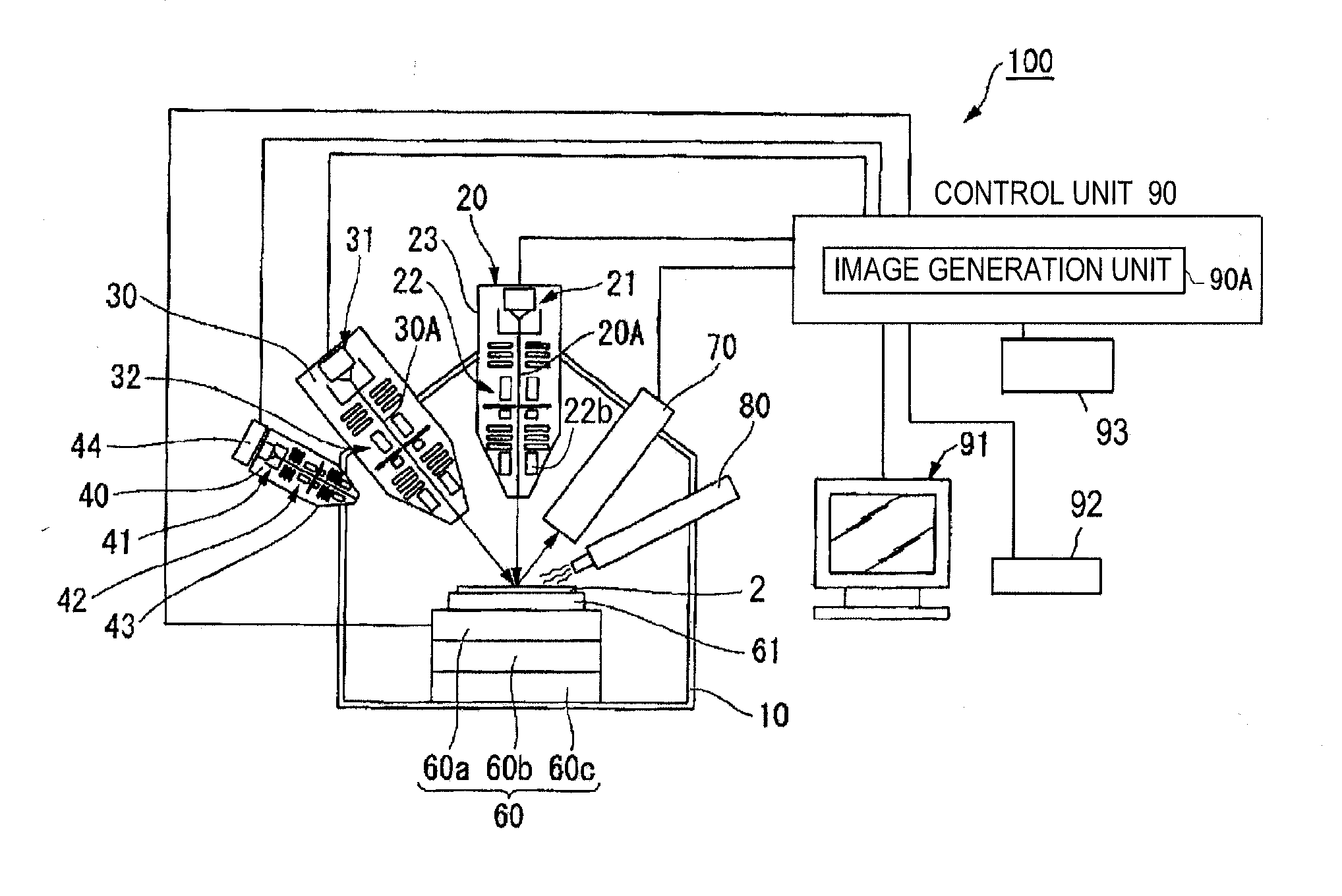
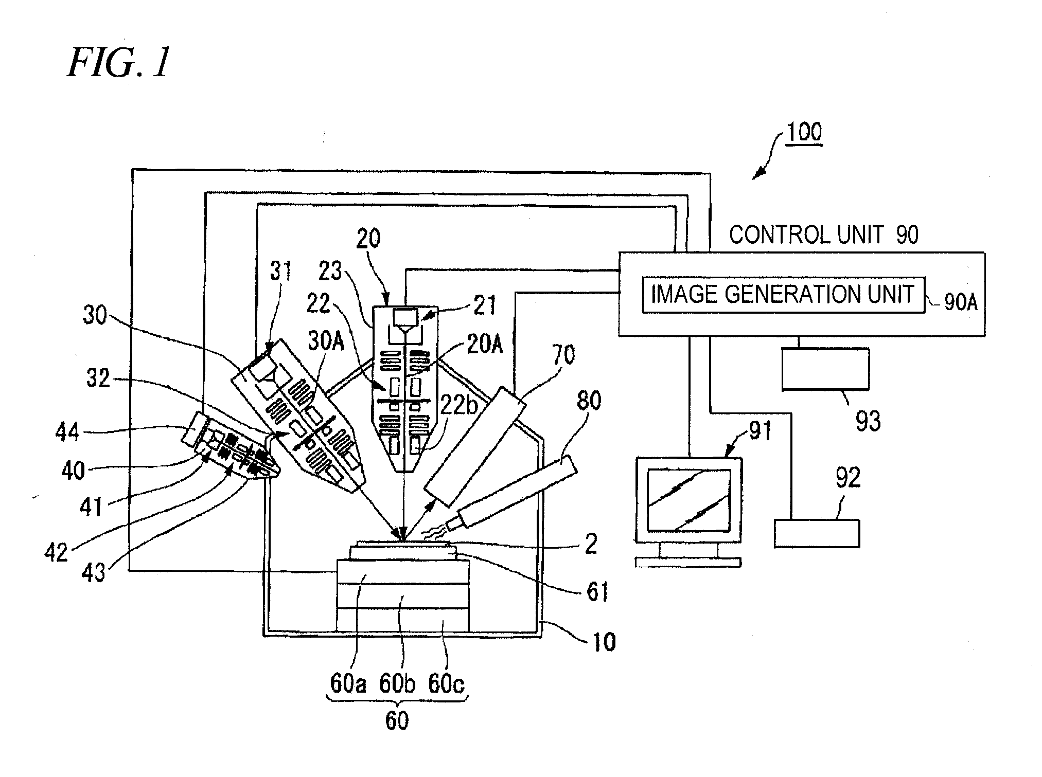
[0038]FIG. 1 is a block diagram showing an entire configuration of a focused ion beam apparatus 100 according to illustrative embodiments of the present invention. In FIG. 1, the focused ion beam apparatus 100 includes a vacuum chamber 10, an ion beam emission system (“focused ion beam emission mechanism” in claims) 20, an electron beam emission system 30, an argon ion beam emission system 40, a sample stage 60, a secondary charged particle detector (“detector” in claims) 70, a gas gun 80, and a control unit 90. An internal pressure of the vacuum chamber 10 is reduced to a predetermined degree of vacuum, and a part or all of component parts of the focused ion beam apparatus 100 are disposed in the vacuum chamber 10.

[0039]The sample stage 60 movably supports a sample base 61, and a sample 2 is placed on the sample base 61. The sample stage 60 includes a movement mecha...


PUM

PropertyMeasurementUnit
sizeaaaaaaaaaa
movement distanceaaaaaaaaaa
transmissionaaaaaaaaaa

Abstract

A focused ion beam apparatus includes: an image generation unit which generates a sample image including location detection marks formed on a sample based on secondary charged particles generated with emission of a focused ion beam to a sample; a display unit which displays a sample image; and a control unit which, in a case of performing working by emitting the focused ion beam to a working region beyond a display range, moves a sample stage, detects locations of the location detection marks included in the sample image after the movement of the sample stage as reference marks from the location detection marks included in the sample image before moving the sample stage, and controls an emission location of the focused ion beam based on the reference marks detected in the sample image after being moved.

Description

[0001]This application claims priority from Japanese Patent Application No. 2013-067320 filed on Mar. 27, 2013 and Japanese Patent Application No. 2014-048446 filed on Mar. 12, 2014, the entire subject-matters of which are incorporated herein by reference.BACKGROUND[0002]1. Technical Field[0003]The disclosure relates to a focused ion beam apparatus which performs working of a sample with a focused ion beam, a method of working a sample using the apparatus, and a computer program for focused ion beam working.[0004]2. Description of Related Art[0005]In the related art, a focused ion beam (FIB) apparatus has been used for performing etching working of a semiconductor device, for example, to obtain a cross section for observation, or for making a sample as a thin piece to manufacture a sample piece for a transmission electron microscope (refer to, for example, Japanese Patent No. 2973211). In addition, in recent years, it is also necessary to perform working of a sample into various sha...

Claims


Application Information

Patent Timeline
Patent Type & Authority Applications(United States)
IPC IPC(8): G01N23/225
CPCG01N23/2258G01N1/32G01N23/2251H01J37/3045H01J37/3056H01J2237/31745
Inventor NAKATANI, IKUKOSATO, MAKOTO
Owner HITACHI HIGH TECH SCI CORP
Why Eureka
Try Eureka