Control unit for robots

a robot control and robot technology, applied in the direction of multiple dynamo-motor starters, motor/generator/converter stoppers, dynamo-electric converter control, etc., can solve the problem of creating a power-excessive state, increasing the power consumption of the driver power circuit itself, and requiring a large torque only in the acceleration period, etc. problem, to achieve the effect of suppressing power loss, reducing size, and enhancing the follow-up performan

Active Publication Date: 2014-10-02
DENSO WAVE INC
View PDF6 Cites 16 Cited by
  • Summary
  • Abstract
  • Description
  • Claims
  • Application Information

AI Technical Summary

Benefits of technology

[0009]Thus, when the motor is driven to be accelerated, the first switch is closed to supplementarily supply power from the backup power circuit to the inverter. Since a part of the power required by the inverter during a period of acceleration of motor speed is supplemented, the inverter can fully drive the motor with the help of the supplemented power, so that the follow-up performance of the motor can be enhanced, while achieving size reduction and suppressing the occurrence of power loss.

Problems solved by technology

This is attributed to the fact that electric power sufficient for meeting required torque is not supplied during the acceleration period, in spite of the fact that the required torque is increasing in the acceleration period.
Further, when the power capacity is increased, power consumption of the driver power circuit itself is also increased.
In practice, however, large torque is particularly required only in the acceleration period.
When these matters are taken into account, designing a drive power circuit with reference to maximum torque may create a power-excessive state in most of the operation period of the robot including a suspension period when the motor is not driven, but for the acceleration period.
At the same time, the increase in power consumption of the drive power circuit may constantly allow unnecessary power consumption (power loss).
In the conventional art, it is difficult to balance the enhancement of the follow-up performance of a motor, with the reduction in the size of the control unit and in the occurrence of power loss.

Method used


Image

  • Control unit for robots
  • Control unit for robots
  • Control unit for robots

Examples


Embodiment Construction

[0019]Referring to FIGS. 1 to 7, hereinafter is described an embodiment of the present invention.

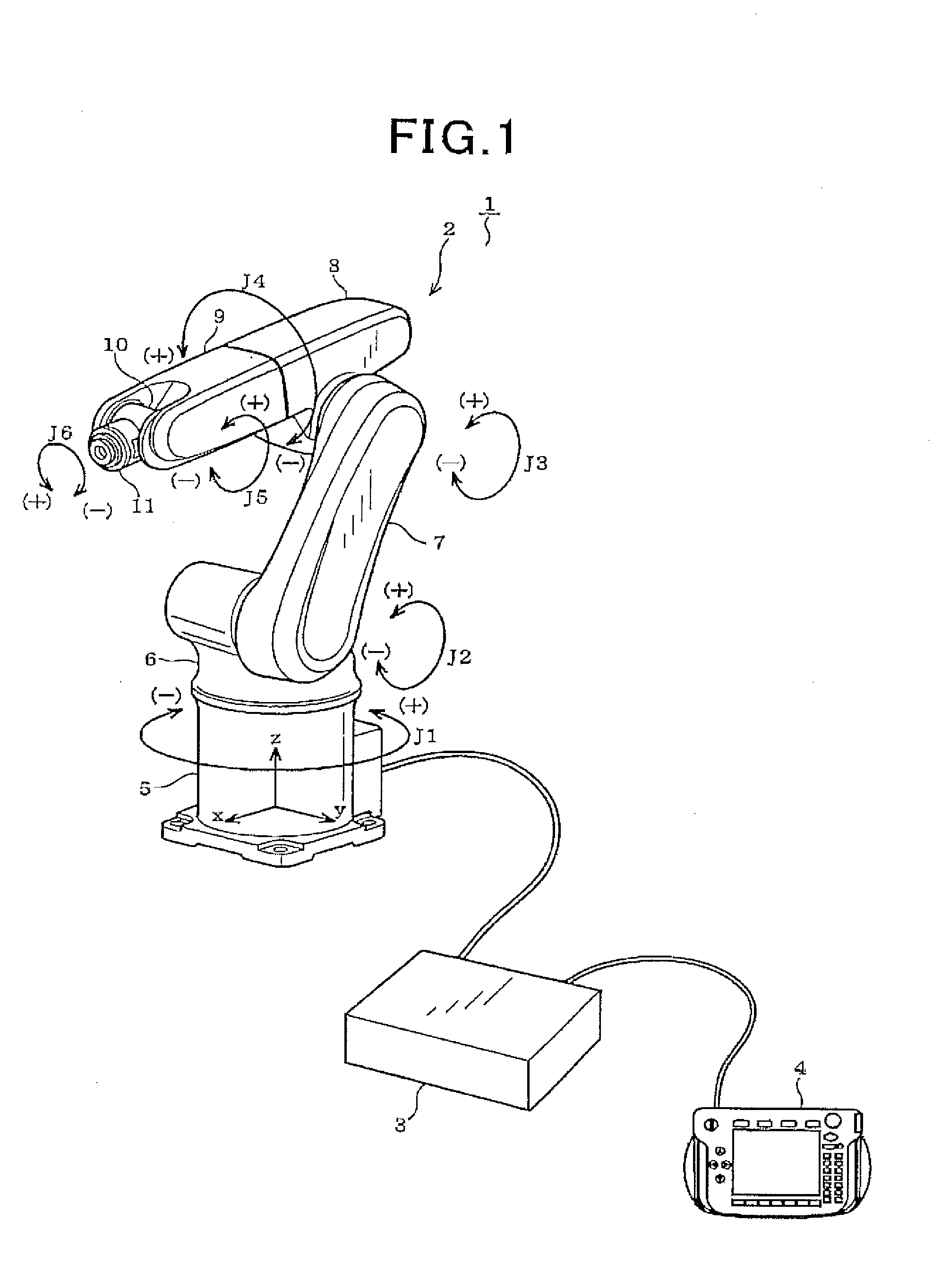
[0020]FIG. 1 illustrates an appearance of a generally used industrial robot system 1 as a target of control in the present embodiment. As shown in FIG. 1, the robot system 1 includes a robot 2, a control unit 3 that controls the robot 2, and a teaching pendant 4 connected to the control unit 3. The teaching pendant 4 may be connected to the control unit 3 only when teaching is carried out, or may be integrally configured with the control unit 3.

[0021]The robot 2 is a so-called six-axis vertical articulated robot having a well-known configuration. Specifically, the robot 2 includes a base 5, shoulder 6, lower arm 7, first upper arm 8, second upper arm 9, wrist 10 and flange 11. The shoulder 6 is arranged on the base 5 and connected thereto via a Z-direction first axis (J1) so as to be rotatable in the horizontal direction. The shoulder 6 is connected, via a V-direction second axis (J2), t...


PUM


Abstract

In a control unit for a robot, an inverter which drives a motor installed in a robot. A control circuit controls drive of the motor. A drive power circuit supplies DC power to the motor, and a control power circuit DC power to the control circuit. A backup power circuit supplies backup DC power to the control circuit when the DC power from the control power circuit to the control circuit is shut down. A first switch is arranged between the backup power circuit and the inverter, the first switch being selectively switched on and off to open and close. A first switch control section switches on the first switch such that the DC power in the backup power circuit is supplementarily supplied to the inverter when the motor is driven to be accelerated.

Description

CROSS-REFERENCE TO RELATED APPLICATION[0001]This application is based on and claims the benefit of priority from earlier Japanese Patent Application No. 2013-066266 filed Mar. 27, 2013, the description of which is incorporated herein by reference.BACKGROUND OF THE INVENTION[0002]1. Technical Field of the Invention[0003]The present invention relates to a control unit for robots, and in particular, to a control unit for controlling speeds of industrial robots.[0004]2. Related Art[0005]As is well known, in a robot, a speed command is outputted from a control circuit and a motor is activated so as to follow the speed command (e.g., see JP-A-2012-223881). During an acceleration period in which the motor is accelerated, the actual speed of the motor is usually slightly different from the speed command value. That is, the actual speed is usually lower than the speed command value. This is attributed to the fact that electric power sufficient for meeting required torque is not supplied duri...

Claims


Application Information

Patent Timeline
Patent Type & Authority Applications(United States)
IPC IPC(8): H02P4/00
CPCH02P4/00H02J1/10H02P23/20
Inventor KANADA, MOTOKI
Owner DENSO WAVE INC
Why Eureka
Try Eureka