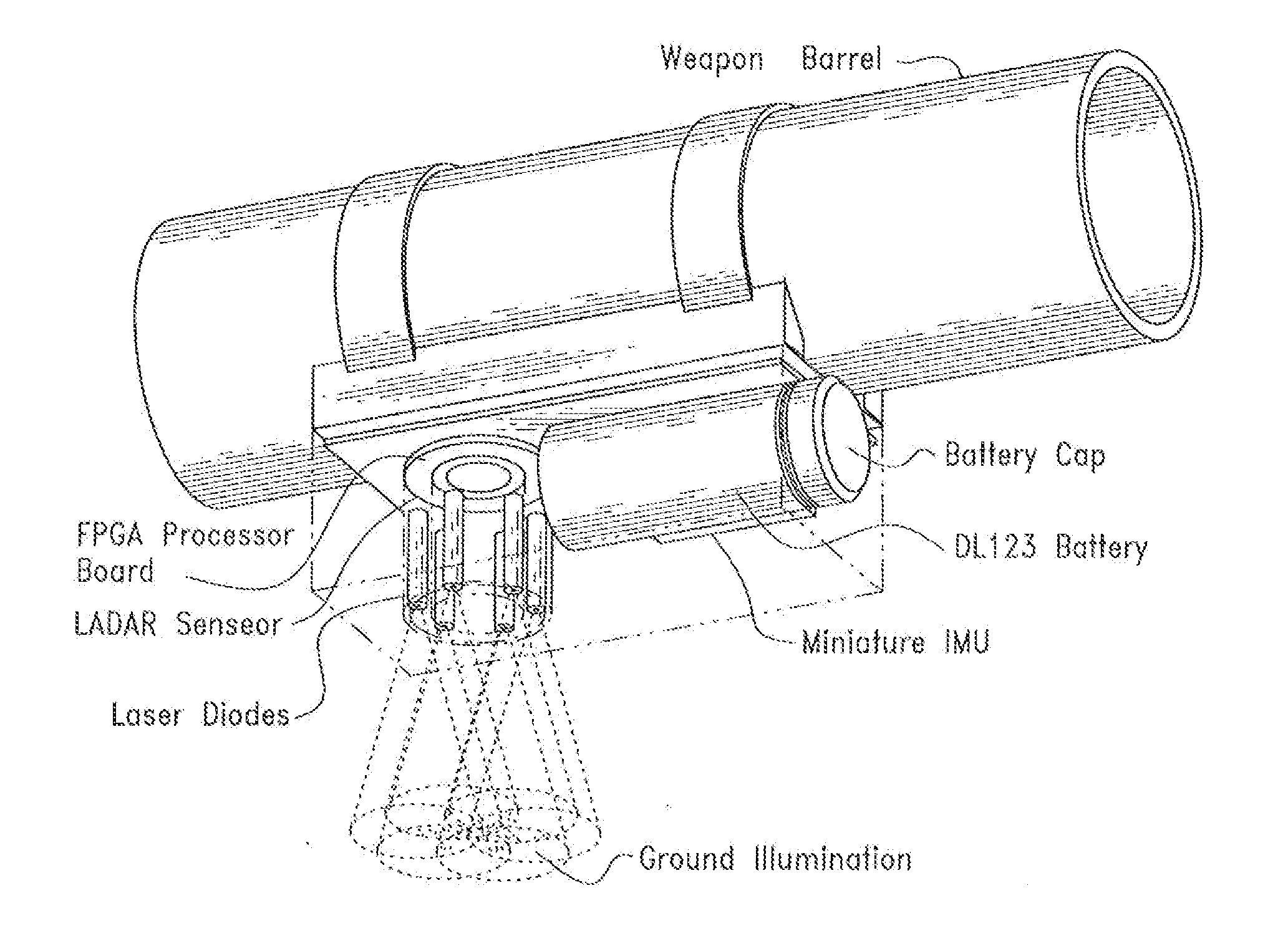
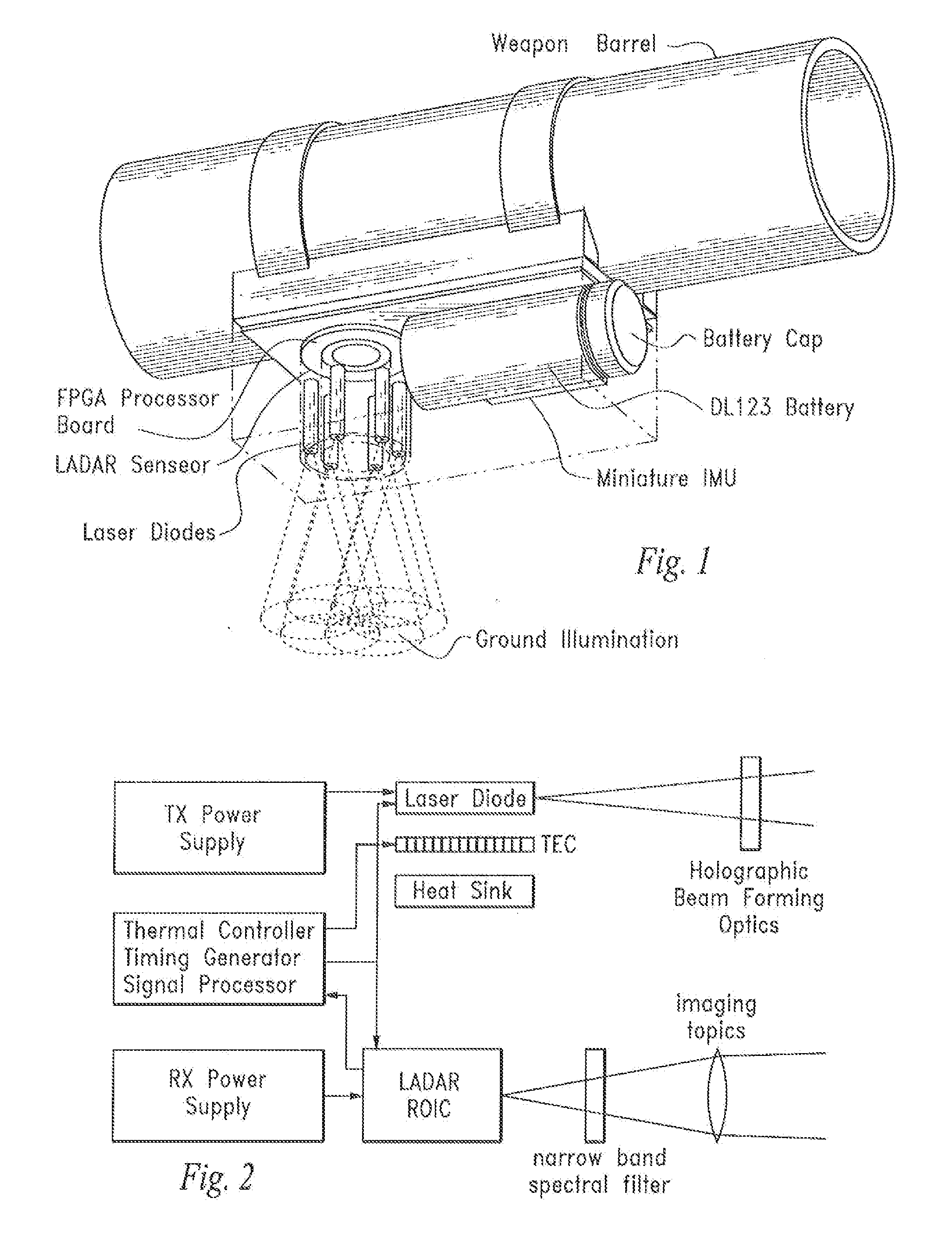
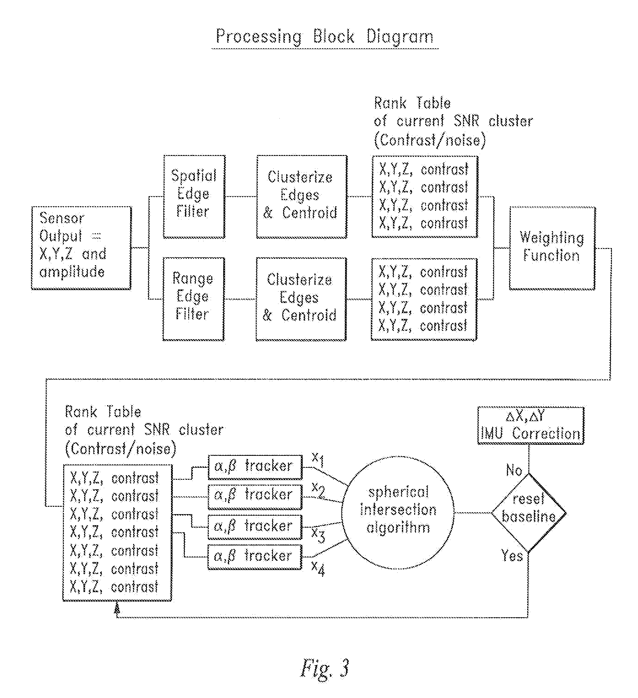
Local Alignment and Positioning Device and Method

a positioning device and positioning technology, applied in the field of positioning devices and positioning devices, can solve the problems of inability to meet demanding military requirements, and large accumulated drift errors of long-loitered uas, etc., and achieve the effect of measuring the range very accurately

Inactive Publication Date: 2014-10-02
PFG IP
View PDF4 Cites 110 Cited by
  • Summary
  • Abstract
  • Description
  • Claims
  • Application Information

AI Technical Summary

Benefits of technology

[0025]The disclosed invention takes advantage of LIDAR measurement in navigation applications. The device and method provide the capability of determining position and self-motion (ego-motion) of a LIDAR system in 3-D space. In a p

Problems solved by technology

When guided solely by inertial sensors, accumulated drift errors for long-loitered UAS quickly become large and unacceptable.
Existing orientation systems include digital magnetic sensors whose accuracy are affected by nearby metal objects and which undesirably require calibration before each use.
Existing miniature and low-power inertial sensors, su

Method used


Image

  • Local Alignment and Positioning Device and Method
  • Local Alignment and Positioning Device and Method
  • Local Alignment and Positioning Device and Method

Examples


first embodiment

[0118]In the first embodiment, all four phase samples are stored in the unit cell. At the end of the integration period these four signals are readout. The integration period could be as long as 33 milliseconds.

second embodiment

[0119]In the second embodiment, only one storage capacitor is used. The signal must be read from the unit cell at four times the transmitted modulation frequency but only to a secondary memory off of the unit cell but within the FPA. After a given integration period (typically 33 milliseconds), the multiple samples can be read out of the FPA.

third embodiment

[0120]In the third embodiment, the output of the amplifier is mixed with a small portion of a phase delayed transmitted waveform. The phase delay of the modulated signal that maximizes the output is the phase delay due to the range.

[0121]In the structured light embodiment, a commercial off the shelf or “COTS” FPA architecture can be used to obtain 3-D imagery for the system, i.e., a COTS visible sensor as an adjunct sensor and a micro-bolometer camera as the main 3-D imaging device.

[0122]FIG. 10 shows an FPA unit cell of a three transistor visible focal plane and a micro-bolometer unit cell.

[0123]The sensor architecture of the structured light 3-D imager embodiment is shown in FIGS. 11A and 11B.

[0124]A micro-bolometer camera is used to obtain both the structured light signal and the imagery signal. Two laser diodes are used to provide the illumination. One diode is transmitted through a diffraction grating. This produces the structure light as a pattern of bright spots. The second l...


PUM


Abstract

A device and method that uses terrain features having one or more predetermined characteristics or weights in an electronic image date frame or set of frames such as a LIDAR voxel set of image data frames for use as system reference points which are, in turn, used in one or more trilateration calculations performed in electronic circuitry to determine a position or ego-motion of the device.

Description

CROSS-REFERENCE TO RELATED APPLICATIONS[0001]This application claims the benefit of U.S. Provisional Patent Application No. 61 / 515,193, filed on Aug. 4, 2011, entitled “Ground Tracking Orientation System” pursuant to 35 USC 119, which application is incorporated fully herein by reference.[0002]This application claims the benefit of U.S. Provisional Patent Application No. 61 / 601,854, filed on Feb. 22, 2012, entitled “GPS-Independent Local Alignment and Positioning Device and Method” pursuant to 35 USC 119, which application is incorporated fully herein by reference.STATEMENT REGARDING FEDERALLY SPONSORED RESEARCH AND DEVELOPMENT[0003]N / ABACKGROUND OF THE INVENTION[0004]1. Field of the Invention[0005]The invention relates generally to the field of electronic imaging devices and positioning devices. More specifically, the invention relates to a tracking and motion sensing device and method that uses terrain features having one or more predetermined characteristics or weights in an elec...

Claims


Application Information

Patent Timeline
IPC IPC(8): G01S17/48
CPCG01S17/48G01S17/36G01S17/66G01S17/89F41G5/26
Inventor HSU, YINGLUDWIG, DAVID
Owner PFG IP
Why Eureka
Try Eureka