Flat-top tunable filter

a tunable optical filter and flat-top technology, applied in the field of tunable optical filters, can solve the problems of henry et al.'s optical filter not being tunable, requiring many mz stages, and affecting the measurement of signal level,

Inactive Publication Date: 2014-10-02
LUMENTUM OPERATIONS LLC
View PDF28 Cites 11 Cited by
  • Summary
  • Abstract
  • Description
  • Claims
  • Application Information

AI Technical Summary

Benefits of technology

[0012]According to another aspect of the present invention there is provided a method of filtering an optical signal comprising: passing an optical signal through a tunable optical filter, the optical signal including a plurality of optical frequency channels, each optical frequency channel having a central frequency substantially centered at a different frequency of predetermined frequency grid having a predetermined grid spacing, the tunable optical filter including: a plurality of sequentially coupled tunable Mach-Zehnder (MZ) interferometers for selecting an optical frequency channel from the plurality of optical frequency channels, each tunable MZ interferometer having a plurality of equidistantly spaced conterminous frequency passbands and frequency stopbands and having a free spectral range substantially equal to an integer multiple of the predetermined grid spacing; a first MZ interferometer optically coupled to the plurality of sequentially coupled tunable MZ interferometers, the first MZ interferometer including first and second interferometer arms optically disposed between first and second optical couplers, the first optical coupler for directing more than 75% of the light received at an input of the first MZ interferometer into the first interferometer arm, the first and second interferometer arms having different lengths; and a controller; and tuning the plurality of sequentially coupled MZ interferometers to have one passband of each MZ interferometer centered on the central frequency of the selected optical frequency channel, and to have at least one of the stopbands of the MZ interferometers centered on the central frequency of each remaining optical frequency channel of the optical signal, so as to suppress each said remaining optical frequency channel of the optical signal; and tuning the first MZ interferometer to have low transmission at the center frequency of the selected optical frequency channel.

Problems solved by technology

Ideally, a tunable filter has excellent crosstalk suppression, since poor crosstalk suppression leads to undesired “leaking” of the optical channels being suppressed, thus impairing the signal level measurements and / or detection and decoding of the selected signal.
Detrimentally, the optical filter of Henry et al. is not tunable.
Unfortunately, the tunable optical filter requires many MZ stages, including stages that have to be repeated, to achieve a satisfactory crosstalk suppression.

Method used


Image

  • Flat-top tunable filter
  • Flat-top tunable filter
  • Flat-top tunable filter

Examples


Embodiment Construction

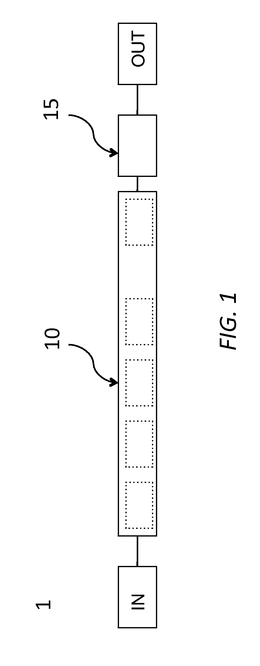
[0032]FIG. 1 is a schematic diagram of a flat-top optical filter according to one embodiment of the instant invention. The flat-top filter 1 includes a cascade of Mach-Zehnder (MZ) interferometers 10 connected in series with another MZ interferometer 15. Each MZ interferometer in the cascade of MZ interferometers 10 is commonly referred to as a stage, a MZ stage, and / or a filter stage.

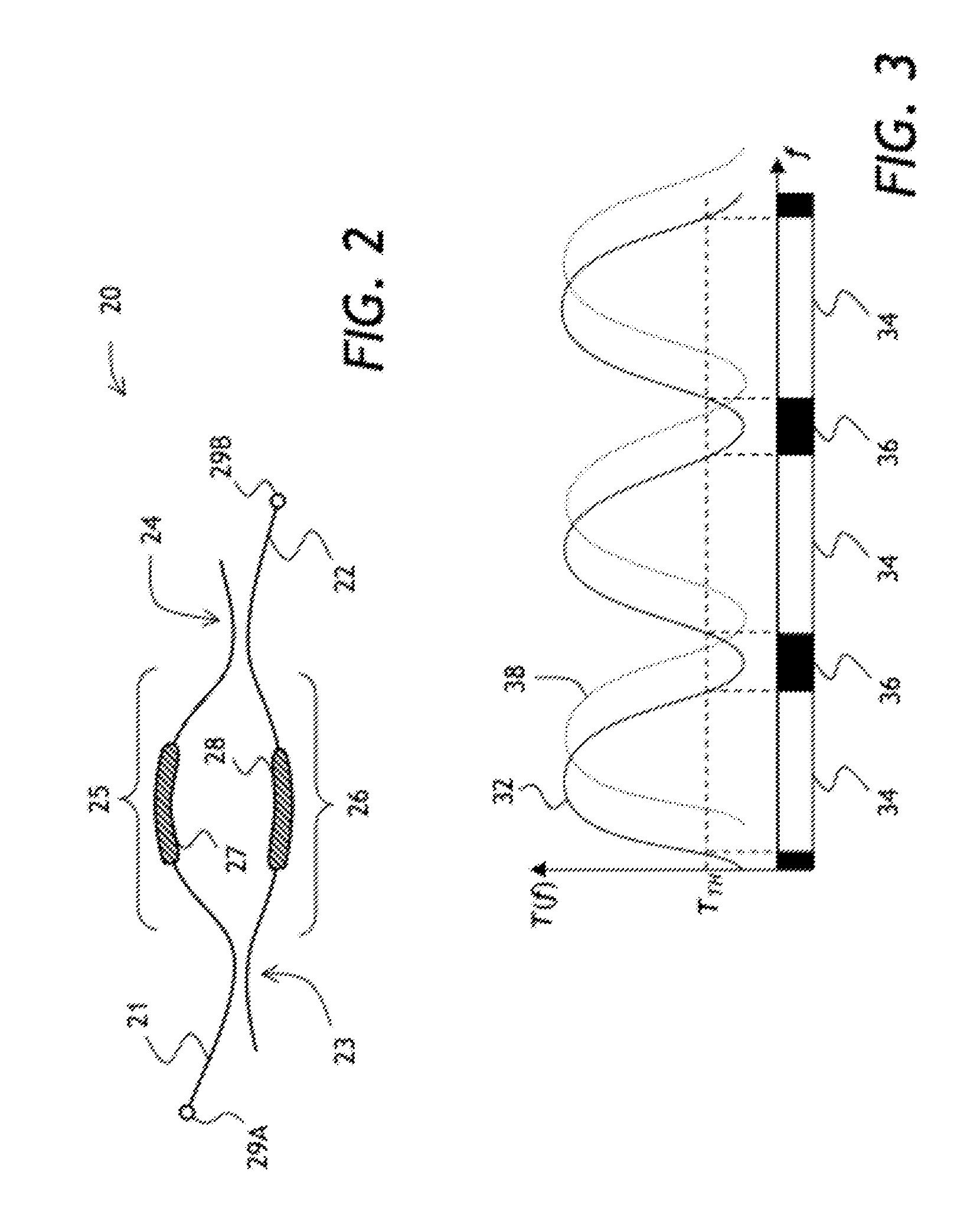
[0033]Referring to FIG. 2, an optical diagram of a MZ interferometer 20, which represents any one of the MZ interferometers in the cascade of MZ interferometers 10, is shown. The MZ interferometer 20 has two waveguides 21 and 22 brought into close proximity to each other at 50%, or 3-dB, evanescent coupler regions 23 and 24, thereby forming two arms 25 and 26. The arms 25 and 26 have a localized heater 27 and 28, respectively, for heating the arms 25 and 26, thereby tuning the MZ interferometer 20 by changing relative optical length of these arms. In general, the tuning range of the heaters will be at ...


PUM

PropertyMeasurementUnit
optical lengthsaaaaaaaaaa
frequencyaaaaaaaaaa
frequencyaaaaaaaaaa

Abstract

A tunable PLC optical filter having sequentially connected thermally tunable Mach-Zehnder (MZ) interferometers is described. The cascade of MZ interferometers, each having a free spectral ranges matching ITU frequency grid spacing, are tuned so as to have a common passband centered on the frequency of the signal being selected, while having at least one of the stopbands centered on any other ITU frequency. Any other optical channel that may be present at any other ITU frequency is suppressed as a result. Another MZ interferometer in series with the cascade of interferometers including an asymmetric or variable coupler, is tuned to have low transmission at the center frequency of the selected optical channel.

Description

TECHNICAL FIELD[0001]The present invention relates to a tunable optical filter, and in particular to a flat-top tunable optical filter having cascaded Mach-Zehnder interferometers.BACKGROUND OF THE INVENTION[0002]Optical filters are often used to select at least one optical frequency band, called a passband, out of an optical frequency spectrum of an optical signal. A central frequency of the passband of a tunable optical filter is adjustable, depending upon a control parameter common to a particular filter type. For example, for a bulk optic tunable filter, the control parameter can be a filter tilt or a clocking (rotation) angle with respect to an incoming optical beam. For an optical waveguide based tunable filter such as tunable Mach-Zehnder (MZ) interferometer, the control parameter can be an electrical signal applied to a localized heater that changes the optical path length of one of its arms, which effectively tunes the MZ interferometer.[0003]Tuning range, spectral selectiv...

Claims


Application Information

Patent Timeline
Patent Type & Authority Applications(United States)
IPC IPC(8): G02F1/21G02F1/01
CPCG02F1/21G02F1/0147G02F1/225G02F2203/055H04B10/25G02F2201/16G02B6/293H04J14/02G02B6/29355H04B10/25891G02F1/212G02B6/29353G02B6/29395H04Q11/0005H04Q2011/0009H04Q2011/0018
Inventor FONDEUR, BARTHELEMYSHEN, JINXIFRENKEL, LEONIDHUA, YIMINWALKER, DAVID R.ZHANG, YUMILINKOVIC, VLATKO
Owner LUMENTUM OPERATIONS LLC
Why Eureka
Try Eureka