High-efficiency candle-type device for filtering ballast water having high-density filter structure

a filter structure and high-efficiency technology, applied in sedimentation settling tanks, vessel construction, separation processes, etc., can solve the problems of affecting the quality of ballast water, difficult to continuously perform a similar level of filtering, and damage to the marine ecosystem of another country, so as to reduce the sealing cost, improve the filtering efficiency, and prevent the original ballast water from being mixed

Active Publication Date: 2014-10-09
PANASIA
View PDF8 Cites 8 Cited by
  • Summary
  • Abstract
  • Description
  • Claims
  • Application Information

AI Technical Summary

Benefits of technology

[0029]The present invention can achieve the following effects by the above-mentioned aspects and configuration, combination, and use that will be described below.
[0030]The present invention is advantageous in that it performs filtering by concentrically installing a filter element in a ballast-water filtering device accommodating a filter portion, and introducing ballast water from a lower end of the filtering device and passing the ballast water through the filter element inside the filtering device, and it discharges backwash water containing foreign substances inside a filter by means of differential pressure, which is created between a suction force and a filter element by rotating the suction portion to be communicated with the filter element by a driving portion that is placed on a lower portion of the filtering device, so that a driving shaft does not pass through a housing body and a space is secured in the housing body to allow the number of filter elements to be increased, thus enhancing filtering efficiency with the ballast-water filtering device of the same volume.
[0031]The present invention is advantageous in that filter elements are arranged along one or more concentric paths having different diameters around a driving shaft, and several filter elements can be simultaneously backwashed via a suction portion having flushing arms as many as the concentric paths, thus considerably improving filtering efficiency.
[0032]The present invention is advantageous in that a driving shaft does not pass through a housing, so that it is unnecessary to maintain air-tightness at upper and lower covers of a housing body and thereby a structure is simple, thus achieving a reduction in sealing cost and preventing original ballast water from being mixed with filtered water due to defective sealing.
[0033]The present invention is advantageous in that it is configured as described above, so that a structure is simplified, thus making it easy to install and obviating the necessity of setting a center of a driving shaft.
[0034]The present invention is advantageous in that it is configured as described above, so that only an upper portion and an upper cover of a housing have only to be removed without the necessity of removing a driving portion even when an inside of the filtering device is repaired or its components are replaced with new ones, thus ensuring convenient maintenance, and in that an entire height of the filtering device is lower as compared to a configuration wherein the driving portion is provided on an upper portion of the filtering device, thus allowing the device to be installed in a relatively small space in a vessel.

Problems solved by technology

However, marine organism species contained in the seawater may cause damage to a marine ecosystem of another country.
However, when this is used as a ballast-water filtering device for a vessel, it is difficult to separate and remove substances contained in seawater, such as microorganisms or jellyfish, from the filter pores via differential pressure because the substances have high viscosity, as a result of which it is difficult to continuously perform a similar level of filtering and thereby filtering efficiency is considerably reduced.
Thus, the rotating shaft b2 occupies a considerable space, so that a space in the filtering device is reduced and thereby it is difficult to accommodate a lot of filters a. Consequently, such a ballast-water filtering device is unsuitable for use in a marine environment, which requires high filtering efficiency.
In this case, since portions on both upper and lower surfaces of the filtering device through which the rotating shaft b2 passes require air-tightness, a structure is complicated, sealing cost is increased, and the original ballast water may be mixed with the filtered water when the sealing is defective.
Further, if the filtering device is configured so that the rotating shaft b2 of the motor b1 passes through the filtering device, it is difficult to keep the balance of the rotating shaft b2 during the installation of the filtering device.
The conventional ballast-water filtering device is problematic in that the motor b1 is provided on the upper portion of the filtering device, so that the entire height of the filtering device should be increased and thereby the filtering device occupies a significant amount of space when installed in the vessel.
However, although the conventional ballast-water filtering device has such an empty space i, the motor b1 is located on the upper portion of the filtering device, such that the limited space of the vessel is inefficiently utilized.
Further, the conventional ballast-water filtering device is problematic in that an operation of removing the motor b1 from the upper portion should be preceded when the inside of the filtering device is repaired or its components are replaced with new ones, thus making it difficult to carry out repair or replacement.
Moreover, the conventional ballast-water filtering device is problematic in that, when the backwash water of the suction portion c flows along the rotating shaft, perfect sealing is not achieved at a position where the rotating shaft b2 passes through the filtering device, so that the backwash water leaks out of the filtering device, and, when the backwash water is accumulated in the discharging portion d, back pressure is created in the discharging portion d, so that a differential pressure between the suction portion c and the filter a is reduced, and thereby smooth backwashing is not achieved and filtering efficiency is lowered.

Method used


Image

  • High-efficiency candle-type device for filtering ballast water having high-density filter structure
  • High-efficiency candle-type device for filtering ballast water having high-density filter structure
  • High-efficiency candle-type device for filtering ballast water having high-density filter structure

Examples


first embodiment

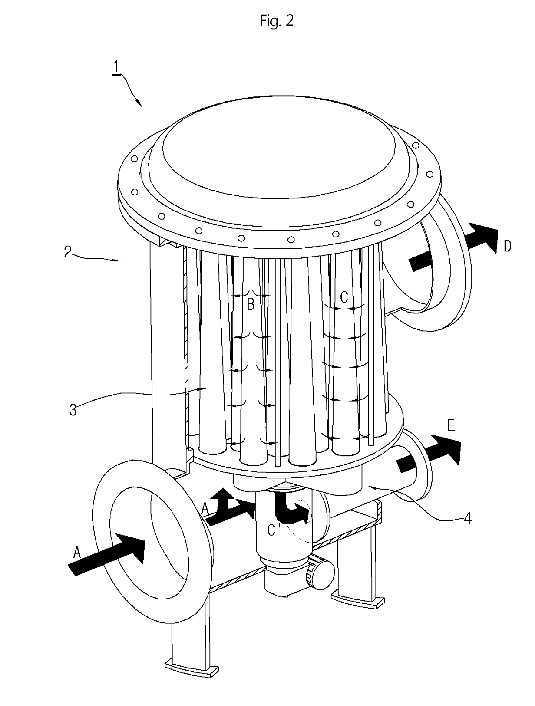
[0118]FIG. 2 is a perspective view showing a candle-type ballast-water filtering device 1 according to the present invention, and FIG. 3 is a vertical sectional view of FIG. 2.

[0119]Referring to FIGS. 2 and 3, the candle-type ballast-water filtering device 1 according to the first embodiment of the present invention may include a housing 2 having an inlet portion 21 and an outlet portion 24 that allows ballast water to flows into and out of a vessel. A filter portion 3 is located in the housing 2 to filter original ballast water introduced through the inlet portion 21. An automatic washing portion 4 functions to wash foreign substances off of the filter portion 3.

[0120]The housing 2 is configured to define a body of the candle-type ballast-water filtering device 1 according to the present invention, and may preferably have a cylindrical shape to accommodate the filter portion 3 for filtering the ballast water while allowing ballast water to flow along an inner wall without being sub...

second embodiment

[0136]Referring to FIGS. 5 to 7, in a candle-type ballast-water filtering device 1 according to the present invention, the suction portion 41 includes the flushing arm 411 that is formed on an end thereof and rotates on the lower cover 232 to communicate with the filter element 31 and thereby suck backwash water, and a flushing body 412 that moves backwash water sucked through the flushing arm 411 and transmits a rotating force from the driving shaft 421 to the suction portion 41.

[0137]The flushing arm 411 is provided on an end of the suction portion 41 and is configured to communicate with the filter element 31 while rotating on the lower cover 232, thus sucking backwash water. Preferably, as the flushing arm rotates around the driving shaft 421 by the driving portion 42 and sequentially communicates with the filter element 31 passing through the lower cover 232, it sucks backwash water containing foreign substances attached to the inner wall of the filter element 31 by the differe...

third embodiment

[0142]Referring to FIG. 9, in a candle-type ballast-water filtering device 1 according to the present invention, the flushing body 412 includes a driving-shaft locking means 413 that locks an end 423 of the driving shaft.

[0143]The driving-shaft locking means 413 refers to all configurations for locking the end 423 of the driving shaft. Preferably, as shown in FIGS. 9 to 11, the locking means includes a bar plate 414 crossing a central line of the flushing body 412, and a locking pin 415 locking the bar plate 414 to the end 423 of the driving shaft. As shown in FIGS. 10 and 11, the bar plate 414 is a rectangular parallel-piped thin plate that horizontally crosses a conduit of the flushing body 412, a coupling hole 427 being formed in the plate so that the locking pin 415 is inserted into the coupling hole to be coupled to the end 423 of the driving shaft. A sufficient sectional area 417 is provided in portions other than the bar plate 414 to permit the movement of the backwash water....


PUM

PropertyMeasurementUnit
densityaaaaaaaaaa
diametersaaaaaaaaaa
restoring forceaaaaaaaaaa

Abstract

A device for filtering ballast water which performs filtering by installing a filter element having a conical shape in a concentric circle direction inside the device for filtering ballast water that accommodates a filter portion, and introducing ballast water from a lower end of the device for filtering and passing same through the filter element inside the device for filtering, and for discharging backwash water containing foreign substances that are inside a filter by way of differential pressure, which is created by a driving portion communicating with a filter element by rotating a suction portion that is located on a lower end of the device for filtering. Particularly, the present invention relates to a high-efficiency candle-type device for filtering ballast water having a high-density filter structure, wherein the driving portion is positioned on a lower portion of a housing so that more filter elements can be accommodated inside the housing.

Description

TECHNICAL FIELD[0001]The present invention relates to a device for filtering ballast water, which is intended to perform filtering by concentrically installing a filter element in the ballast-water filtering device accommodating a filter portion, and introducing ballast water from a lower end of the filtering device and passing the ballast water through the filter element inside the filtering device; and to discharge backwash water containing foreign substances inside a filter by means of differential pressure, which is created between a suction portion and a filter element by rotating the suction portion located on a lower end of the filtering device to be coupled with the filter element via a driving portion. More particularly, the present invention relates to a high-efficiency candle-type device having a high-density filter structure for filtering ballast water; wherein: the driving portion is positioned on a lower portion of a housing so that more filter elements can be accommod...

Claims


Application Information

Patent Timeline
Patent Type & Authority Applications(United States)
IPC IPC(8): B01D29/68B01D29/66
CPCB63J4/002B01D29/117B01D29/682B01D29/668B01D2201/02B01D29/52B01D29/11B01D29/62B63B13/00B01D29/54B01D2201/0438
Inventor LEE, SOO-TAEPYO, TAE-SUNGLEE, SU-KYU
Owner PANASIA
Why Eureka
Try Eureka