Liquid cooled stator for high efficiency machine

Active Publication Date: 2014-10-09
LC ADVANCED MOTOR TECH CORP
View PDF33 Cites 27 Cited by
  • Summary
  • Abstract
  • Description
  • Claims
  • Application Information

AI Technical Summary

Benefits of technology

This patent describes a cooling system for a rotating machine that uses specialized wound windings and a cooling manifold. The preferred design uses either Edge Form Wound Windings or Diamond Form Wound Windings for distributed wound machines. By placing the cooling manifold in the center of the slot between two sets of windings, the system achieves better thermal performance and allows for higher current density and torque density of the rotating machine. The cooling system also uses metallic vessels that contain the liquid cooling medium for high reliability. The overall approach results in a compact, efficient, reliable and low-cost design.

Problems solved by technology

Two phase cooling has not developed into a mainstream due to cost and complexity.
This design cools the stator better than air, but is limited by i) the conductivity between the jacket and the stator, ii) the poor conductivity of the stator laminations, iii) the conductivity of the slot liners, and iv) the poor conductivity between the winding and the slot liners.
Either of these has similar but not as severe disadvantages to the cooling jacket design.
These have the disadvantage of either being overly complex or having the fluid cause drag between the rotor and the stator.
This has the disadvantage of requiring a special fluid and some complex manufacturing methods to provide the fluid channel.
These windings typically require some relatively complex end turns to wire them properly.
For the more typical internal rotor configuration, assembly is a bit trickier because even with relatively open slots, the opening is smaller than the slot.
This is further complicated if the slot opening is made smaller for motor performance reasons.
The challenge with any stator lamination design that has separate teeth is to secure the teeth structurally so they do not move or break.
Even small movements of the teeth can cause acoustic noise.
A second challenge is to configure the joint in such a way to not significantly disturb the magnetic flux traveling through the laminations.
This is the easiest method of stator winding, but results in the lowest amount of conductor in the slot and therefore the lowest efficiency.
This is typically the most labor-intensive type of winding due to the manufacture of the coils and the insertion time to put these coils in the machine from the inside.
This is not typically used for distributed windings because you are not able to bobbin wind a coil and then insert it into a stator assembly.
This facilitates simpler winding, but one disadvantage of this is the eddy current losses due to slot leakage can be significantly higher.

Method used


Image

  • Liquid cooled stator for high efficiency machine
  • Liquid cooled stator for high efficiency machine
  • Liquid cooled stator for high efficiency machine

Examples


Embodiment Construction

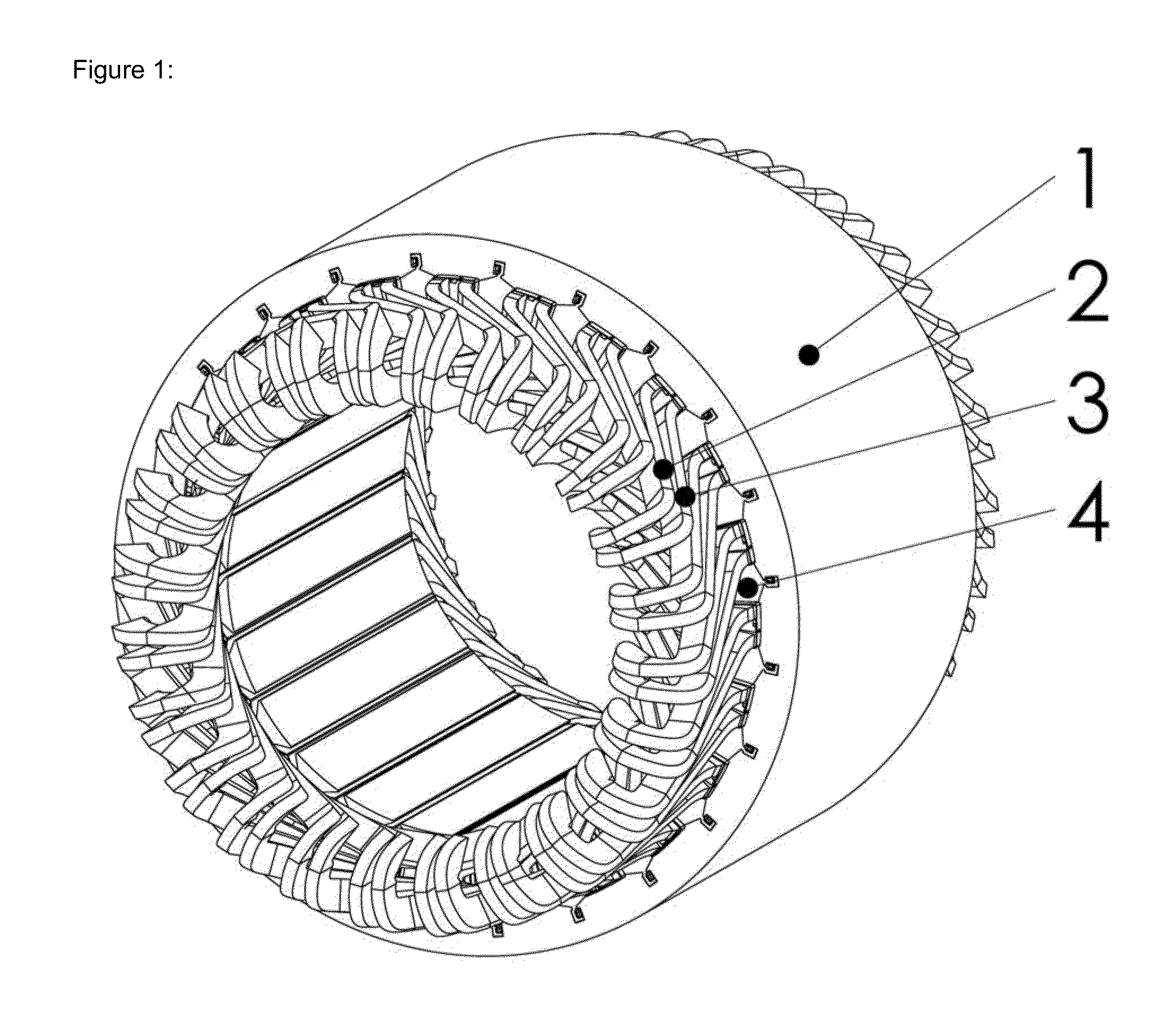
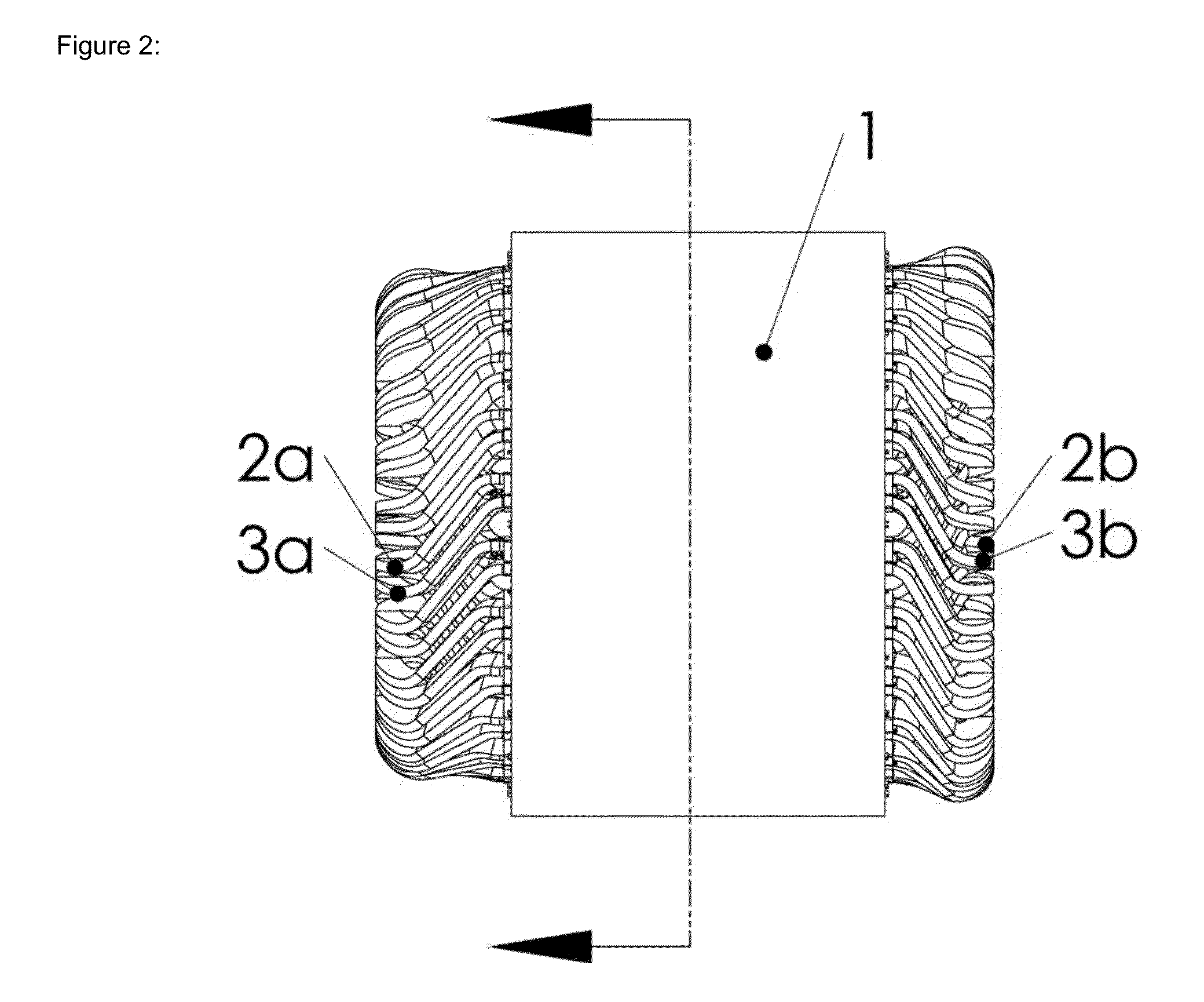
[0029]Referring particularly to FIG. 1, a distributed wound stator assembly is shown containing stator yoke 1, stator coil 2, stator coil 3, and stator lamination teeth 4. There are two different stator coils 2,3 shown due to the fact that they are not evenly spaced and therefore are of slightly different shape. In order to accommodate assembly of the machine the coils 2,3 are bent inward on at least one end as shown in FIG. 2 where coil ends 2a,3a are bent inward and coil ends 2b,3b are bent in a more conventional configuration. The joint between the stator teeth 4 and stator yoke 1 can be seen clearly in FIG. 3.

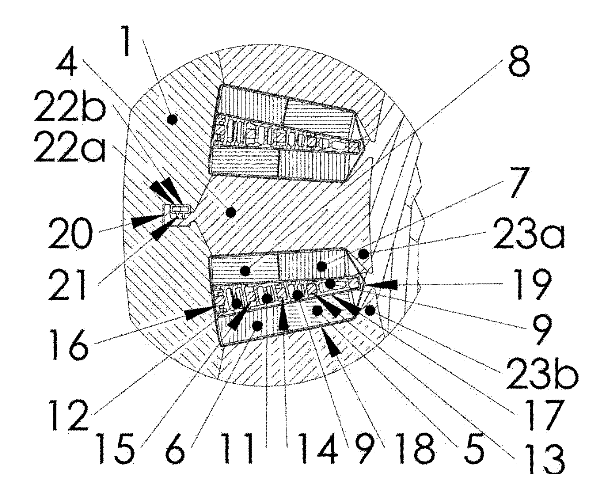
[0030]In the cross section view of FIG. 4, the coil bundles can be seen as 5,6,7, and 8. Each of these coil bundles can be made up of anywhere from a single turn to many turns. The wire is rectangular in shape with the wide dimension on the wire being in the circumaxial direction of the machine. This is the same direction as the narrow dimension on the coil bundle as shown ...


PUM

PropertyMeasurementUnit
Electrical conductivityaaaaaaaaaa
Currentaaaaaaaaaa

Abstract

A stator for a motor, generator or the like that is liquid cooled using glycol or similar fluid with the cooling applied directly in the winding slots of the stator in either concentrated wound or distributed wound configurations.

Description

BACKGROUND OF THE INVENTION[0001]Stators for rotary electric machines including electric motors, generators, and the like have employed various types of cooling including air, liquid and two phase cooling. Air blown through the center of the machine had traditionally been the standard with liquid becoming more common in high power applications. Two phase cooling has not developed into a mainstream due to cost and complexity. Liquid cooling is preferred for many high power applications because it generates a more compact design and is compatible with a sealed housing construction which is preferable in many environments.[0002]The most common liquid cooling design uses a cooling jacket wrapped around the outside of the stator assembly. This can be seen in U.S. Pat. No. 5,448,118 entitled LIQUID COOLED MOTOR AND ITS JACKET, included herein by reference. In this design there is an aluminum extrusion that surrounds the outside of the stator and has passages for cooling fluid to pass thro...

Claims


Application Information

Patent Timeline
IPC IPC(8): H02K9/19H02K15/02
CPCH02K15/024H02K9/19H02K3/24Y10T29/49009H02K9/197
Inventor MARVIN, RUSSEL HUGH
Owner LC ADVANCED MOTOR TECH CORP
Why Eureka
Try Eureka